
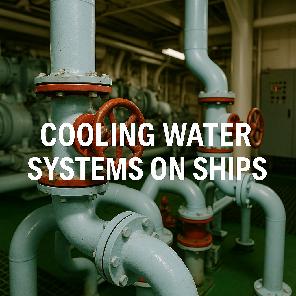
Understand how seawater and freshwater cooling circuits protect ship machinery, how their main components work, and what engineers should monitor during operation.
An engine room produces heat continuously. Main engines, generators, compressors, and other machinery depend on effective cooling to keep their operating temperatures within safe limits. A restricted sea suction or a poorly vented freshwater circuit can therefore affect much more than one piece of equipment.
Marine cooling water systems carry heat away from machinery and transfer it to seawater through heat exchangers. Understanding this heat path helps engineers and cadets connect temperature readings with the condition of pumps, valves, coolers, and the machinery itself.
Why Cooling Matters: Maintaining the Right Temperature
Effective cooling means maintaining the temperature specified for each component. Excessive temperatures can damage lubricants, seals, and engine parts. Excessive cooling can also be harmful: it can affect combustion conditions and, in susceptible engines, contribute to cold corrosion.
Cooling systems therefore support machinery reliability and efficient operation. They also create opportunities to recover useful heat, provided that the engine’s temperature requirements remain satisfied.
For an engineer on watch, the objective is to understand whether the system is maintaining the correct conditions—and recognise changes before they develop into machinery failures.
How a Central Cooling System Works
In a central cooling arrangement, seawater circulates through a limited section of piping and removes heat from treated freshwater in one or more central coolers. The two fluids remain separated by the heat exchanger surfaces.
A common arrangement contains three circuits:
| Circuit | Main function | Typical equipment served |
|---|---|---|
| Seawater circuit | Carries heat from the central cooler to the sea | Seawater side of the central cooler |
| Low-temperature freshwater circuit (LT) | Receives heat from machinery coolers and transfers it to the central cooler | Lubricating oil coolers, charge air coolers, and jacket water coolers |
| High-temperature freshwater circuit (HT) | Controls the temperature of engine components exposed to combustion heat | Cylinder liners, cylinder heads or covers, and certain exhaust valve arrangements |
Where a separate jacket water cooler is fitted, heat passes from the engine’s HT circuit to the LT circuit, and then from the LT circuit to seawater. Other installations combine or interconnect cooling flows differently. The ship’s piping diagram establishes the actual arrangement.
Central Cooling Compared with Distributed Seawater Cooling
Some vessels supply seawater to several individual machinery coolers. Central cooling reduces the extent of seawater piping and concentrates much of the corrosion and marine growth exposure around the seawater circuit.
However, shared cooling equipment can serve several consumers. A fault in a central cooler or common seawater supply may therefore affect multiple machines. Isolation arrangements, standby pumps, and available cooling capacity deserve careful attention.
Jacket Water: The Engine’s High-Temperature Circuit
Jacket water circulates through cooling passages around engine components such as cylinder liners and heads. A pump maintains circulation, while a temperature control valve regulates how much water passes through a cooler or bypasses it.
Depending on the installation, the valve may mix flows or divert them. Its sensor may regulate an inlet or outlet temperature. These details should be checked against the engine manual and system diagram.
There is no single jacket water temperature suitable for every marine engine. Starting conditions, operating temperatures, alarm limits, and shutdown settings must come from the relevant engine documentation.
For example, MAN’s L27/38 guidance distinguishes between HT and LT circuits and explains the importance of maintaining suitable temperatures and preheating when operating on heavy fuel oil.
An elevated expansion tank normally connects to the circuit through make-up and vent arrangements. The full circulating flow should not be assumed to pass through the tank.
Low-Temperature Cooling and Charge Air Coolers
The LT circuit supplies equipment that requires a lower cooling-water temperature than the engine jacket circuit.
A charge air cooler removes heat from compressed intake air after the turbocharger. Cooling increases air density and helps maintain the engine’s intended air supply. Restricted water flow or deposits on either side of the cooler can reduce its performance.
The air side and water side need separate attention. Condensate drains and water separators, where fitted, also matter because accumulated water can be carried towards the engine.
Some engines use staged charge air cooling with both HT and LT connections. Identify the arrangement before interpreting a temperature reading or changing a valve setting.
Piston Cooling: Identify Whether the Engine Uses Oil or Water
Piston crowns require cooling, but a dedicated piston cooling water system is not a universal feature of marine engines.
Oil cooling is used in many modern engines. WinGD’s X92 installation guidance, for example, places piston cooling within the main lubricating oil system, while Wärtsilä’s 31SG guide describes an oil-cooled piston top.
Water-cooled piston arrangements exist on certain engine designs. Their monitoring and maintenance requirements must be taken from the specific manual.
For cadets, the practical lesson is to identify the cooling medium first. A piston cooling problem on an oil-cooled engine requires investigation of the relevant oil supply, pressure, temperature, and passages.
Pumps, Heat Exchangers and Expansion Tanks
Cooling Water Pumps
Seawater pumps move water through the open circuit. Freshwater pumps circulate coolant through the closed circuits. Depending on the installation, pumps may be electrically driven, engine driven, or provided in a combination of arrangements.
A discharge pressure reading alone does not prove adequate circulation. Interpret it alongside suction conditions, flow indications, temperatures, and valve positions.
Noise, vibration, and fluctuating pressure can indicate cavitation or air ingress. Possible causes include a restricted suction strainer, inadequate intake submergence, or an unsuitable valve arrangement.
Central Coolers and Other Heat Exchangers
Plate heat exchangers provide a large heat-transfer area within a compact installation. Shell-and-tube coolers are also used, depending on the service and vessel design.
In a gasketed plate cooler, adjacent passages carry the two fluids without mixing. Counter-current flow supports efficient heat transfer and a close temperature approach.
For a central freshwater cooler, the approach temperature commonly means the difference between the freshwater outlet temperature and seawater inlet temperature.
A widening approach temperature may indicate deteriorating performance, but it must be assessed alongside machinery load, seawater temperature, and flow conditions. A rising pressure drop can suggest restricted passages; fouling can also reduce heat transfer without a large pressure-drop increase.
When reassembling a gasketed cooler, follow the specified plate order, tightening sequence, and plate-pack dimension, often called the A-dimension. Generic bolt-torque instructions are insufficient.
Expansion Tanks
In a conventional elevated arrangement, the expansion tank accommodates changes in coolant volume, provides static head, and receives air from connected vent lines.
Check its level and condition regularly, but interpret changes carefully:
- A falling level may indicate leakage or air leaving the system after maintenance.
- A rising level may reflect normal warming, excessive make-up, or fluid entering through a leaking heat exchanger.
- Oil contamination suggests a fault requiring investigation.
- Persistent bubbling may indicate air ingress or, depending on the engine, combustion gas leakage.
Tank level alone does not establish the cause of a fault.
Freshwater Treatment: Clean Water Still Needs Protection
A closed circuit needs suitable make-up water and an approved treatment programme. Untreated freshwater can contribute to corrosion and deposits even when it looks clear.
Use the engine manufacturer’s water-quality limits and an approved inhibitor compatible with the system’s materials. Nitrite-based products are one option; other approved chemistries are also available. Oxygen scavengers and antifreeze should not be added automatically.
For nitrite-based treatment, routine checks commonly include inhibitor concentration, pH, and chloride content. Wilhelmsen’s Engine Water Treatment guidance stresses suitable make-up water, regular testing, and compliance with engine manufacturer recommendations. Its numerical treatment limits apply to that particular product.
Keep records of test results, chemical additions, and make-up water consumption. Repeated top-ups can dilute treatment and conceal a leak. Good appearance alone does not confirm correct chemistry.
Seawater Fouling and Corrosion
The seawater circuit is exposed to organisms, suspended solids, and debris. Sea chests and strainers provide the first barrier, while a marine growth prevention system may limit biological fouling.
Effective maintenance combines suction inspections, strainer cleaning, cooler performance monitoring, and servicing of the installed prevention equipment.
Back-flushing or chemical cleaning should follow the cooler manufacturer’s procedure. Treatment methods and discharge conditions must also suit the vessel and its operating location.
Cleaning decisions should use performance trends alongside the planned maintenance schedule. Frequent temperature alarms are a late indication of a problem that may have been developing for some time.
Practical Operation: Before Starting, Underway and After Stopping
Before Starting Machinery
Confirm that maintenance is complete and the correct pumps, coolers, and valves are available. Check freshwater level, treatment condition, and venting, particularly after draining or opening the circuit.
Establish the required circulation and verify cooling supply to the equipment about to start. Confirm seawater flow where needed and preheat the engine to its specified starting condition.
Check standby pump readiness and relevant alarms according to the vessel’s procedures.
During the Watch
Record enough information to explain a change in performance:
| Reading or observation | What it helps reveal |
|---|---|
| HT inlet and outlet temperatures | Jacket water condition and temperature control response |
| LT supply and return temperatures | Cooling available to connected consumers |
| Seawater inlet temperature | Changes in external cooling conditions |
| Pump suction and discharge pressures | Possible suction restrictions or abnormal hydraulic conditions |
| Cooler and strainer pressure drops | Developing restrictions, when compared at similar flow |
| Expansion tank level and make-up | Leakage, venting, or abnormal fluid entry |
| Charge air and lubricating oil temperatures | The effect of cooling performance on machinery |
| Machinery load | Whether temperature changes follow increased heat demand |
Compare readings under similar conditions. A temperature rise during increased engine load needs a different interpretation from a rise at unchanged load and seawater temperature.
Manoeuvring, Low Load and Shutdown
At low load, temperature control valves may increase bypass flow to prevent excessive cooling. Required circulation must still be maintained.
After shutdown, continue circulation and preheating as specified for the engine. Longer lay-up requires a preservation plan suited to the vessel’s climate, materials, and treatment programme.
–
Troubleshooting Common Cooling Problems
Protect affected machinery first, then investigate the heat path systematically. Load reduction, standby equipment changeover, or stopping machinery should follow the applicable alarm response and operating procedures.
| Symptom | Possible causes | Initial checks |
|---|---|---|
| Jacket outlet temperature rises at steady load | Reduced circulation, trapped air, faulty temperature control, or inadequate heat rejection | Confirm the reading; check HT circulation, valve response, and LT temperatures |
| Several LT consumers become hotter together | Shared seawater supply restriction, central cooler problem, or insufficient LT circulation | Check seawater suction, strainers, common pumps, and central cooler performance |
| One machine overheats while others remain normal | Local branch restriction, local cooler fault, or machine-specific problem | Compare branch temperatures, local valves, and cooler condition |
| Charge air temperature rises | Air-side deposits, reduced cooling-water flow, warmer LT supply, or changed engine conditions | Check both sides of the cooler and interpret temperatures against load |
| Expansion tank repeatedly needs topping up | External leakage, internal leakage, or incomplete venting | Inspect for leaks; check connected oil systems and review recent maintenance |
| Chloride content increases | Unsuitable make-up water or seawater contamination | Test make-up water and investigate the relevant heat exchanger |
| Pump becomes noisy and pressure fluctuates | Cavitation, air ingress, or a suction restriction | Check suction pressure, intake conditions, strainers, and valve positions |
| Plate cooler leaks externally | Damaged gaskets, plate misalignment, incorrect compression, or pressure transients | Isolate and inspect; verify the specified assembly procedure |
Avoid diagnosing a cooler leak solely from expansion tank level. The direction of leakage depends on the pressure difference between the fluids and may change when pumps stop.
–
An Illustrative Training Scenario
The following is a teaching example, rather than a documented vessel incident.
Following cooling-system maintenance, an engineer notices a rising HT outlet temperature while the LT supply remains near its normal value. The expansion tank also needs topping up.
Several explanations remain possible: trapped air, reduced HT circulation, an incorrect valve position, or a temperature control fault. Normal LT temperature makes a major shared LT cooling problem less likely, but does not establish the cause.
The useful training task is to choose the next checks and explain why each reading matters. This develops stronger diagnostic habits than memorising “high temperature means a dirty cooler.”
–
Cooling Efficiency and Heat Recovery
Cooling consumes auxiliary power. Clean heat-transfer surfaces and suitable pump operation help avoid unnecessary energy use.
Variable-speed control can reduce excessive pumping in suitable installations, but minimum flows and equipment requirements must be preserved. Savings should be established for the vessel’s actual duty profile.
HT water may also provide useful heat for a freshwater generator or other recovery equipment. Heat recovery must remain compatible with engine temperature control.
Additional sensors and automated monitoring can support earlier fault detection. Their value depends on reliable measurements, suitable baselines, and engineers who understand the circuit.
Frequently Asked Questions
Is jacket water the same as central cooling?
Jacket water is the engine cooling circuit. Central cooling describes the wider arrangement through which machinery heat is ultimately transferred to seawater.
Does seawater enter the engine’s jacket passages?
In a conventional central cooling arrangement, the jacket circuit contains treated freshwater. Seawater remains on the other side of the relevant heat exchanger.
Do all marine engines have piston cooling water?
No. Identify the engine’s cooling medium from its manual; many engines use oil for piston cooling.
How can I recognise a fouled cooler?
Compare heat-transfer performance and pressure drop with a clean baseline at similar load and flow. One temperature reading is insufficient.
How often should cooling water be tested?
Follow the engine instructions, treatment supplier’s guidance, and vessel maintenance programme. Testing frequency may need to increase after maintenance, contamination, or substantial topping up.
Should a leaking plate cooler simply be tightened?
Inspect the cause and follow the manufacturer’s closing procedure. Excessive or uneven compression can damage the plate pack or seals.
–
Reliable Cooling Starts with Understanding the Circuit
A reliable cooling system depends on circulation, heat transfer, temperature control, and water quality working together.
For engineers and cadets, three habits are especially useful: trace the actual heat path, compare operating trends, and investigate unexplained make-up water consumption. They help turn cooling readings into evidence for timely maintenance and informed decisions on watch.
References and Further Reading
- Wärtsilä — Central Cooling Water System
- MAN Energy Solutions — L27/38 project guidance
- WinGD — X92 Marine Installation Manual
- Wärtsilä — 31SG Product Guide
- Alfa Laval — Marine gasketed plate heat exchangers
- Alfa Laval — Gasketed plate heat exchanger closing procedure
- Wilhelmsen — Engine Water Treatment 9-108