
Large ship main engines cannot be started by battery or hydraulic systems; they require compressed air at sufficient pressure and volume. The starting air system therefore includes air compressors, air receivers, and the associated piping, valves, and controls needed to store and supply compressed air to rotate the engine for starting. This system provides the starting air to the engine cylinders in the correct firing order and also enables slow turning and routine operational checks.
The starting air system supplies clean, dry compressed air at about 30 bar from air receivers to rotate a large two-stroke main engine for starting. Its main components include the main starting valve, pneumatic actuators, non-return valve and flame arrester, main manifold, cylinder air start valves, distributor and timing valves, and a slow-turning bypass valve. The system admits starting air to the cylinders in the correct firing order, must be capable of starting the engine from any position, and requires adequate drains, relief protection, flame arresters or bursting caps, and regular checks for leaking cylinder starting air valves.
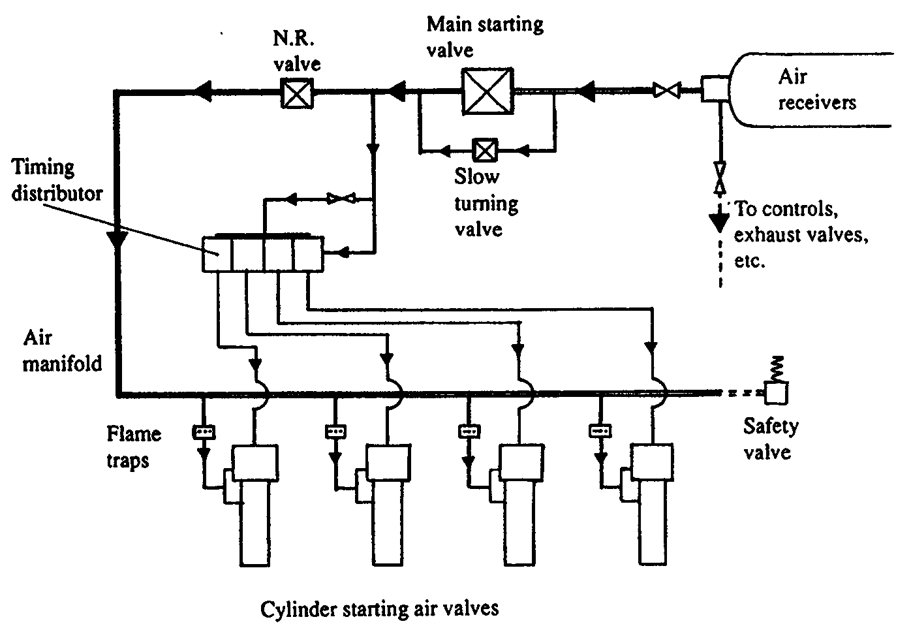
Figure below shows a starting air system for a large two-stroke engine. Clean, dry, compressed air at starting pressure (30 bar) is stored and supplied to the system from air receivers. The main starting valve (automatic valve) is operated by a pneumatic actuator, and similar actuator controls are fitted for slow-turning and to the distributor or timing valves. The main starting valve can be locked shut and this must be done before the engine turning gear is engaged. When this valve is open, air passes through a non-return valve and flame arrester to the main manifold supplying pressure to the cylinder valves, one of which is fitted to each cylinder of the engine.
The cylinder air start valves are normally held closed by a compression spring together with cylinder pressure acting over the valve lid. Air from the manifold enters these valves where it forms a pressure balance between the underside of the valve lid and a balance piston of equal area on the valve spindle. Consequently this does not cause the valve to open.
Cylinder valves are opened when operating air, transmitted from the distributor, applies pressure to the larger operating piston on the valve spindle. As the valve is forced open, starting air from the manifold enters the cylinder, applying pressure on the piston and causing the engine to rotate in the corresponding direction. To close the cylinder valves the connection from the distributor is opened to atmosphere, allowing the spring to close the valve and return the operating piston.
Air from the main valve also passes through two connections to the distributor. One depresses each timing valve in the distributor from its free position to engage it with the timing cam. This line can be blocked for test purposes or by safety cutouts. Until air pressure is applied, the timing valves are held clear of the cam by springs.
The second connection supplies air to the operating ports, from which it will pass through any timing valves which are open, to the corresponding cylinder valves, causing them to open. Air from the manifold will then enter that cylinder to start the engine. The timing valve for each cylinder is synchronised with the engine position and successive valves operate in the firing order.
On large engines a slow-turning valve can bypass the main starting valve and will supply just enough air to rotate the engine slowly. This is used to turn the engine through one revolution while the indicator cocks are kept open, when preparing for sea. At any subsequent time, if the engine has not been used for about half an hour the slow-turning valve should be used to turn the engine slowly for one revolution before opening the main valve for a normal start.
Starting air is shut off from the engine as soon as sufficient starting speed has been reached; fuel is then applied and engine speed increased.
A main engine must be capable of starting from any position and it is normal to have starting valves in each cylinder. Multi-cylinder Vee type engines may only require starting valves to be fitted to one bank of cylinders.
Adequate drains must be fitted to the air start system to keep it free of oil or water. A safety or relief valve is fitted to the main air manifold. Flame arresters or bursting caps or discs must be fitted to each cylinder valve connection from the manifold in reversible engines. Non-reversing engines require one only, fitted between the non-return valve and the engine.
Checks must be made that cylinder starting air valves do not leak. These can be carried out while the engine is running by feeling the temperature of the air pipe adjacent to the valve (see Chapter 7 on explosions in air start systems). Tests while the engine is stopped require starting air to be applied and the main valve opened, after first blocking off air to the timing valves. Pressure will escape into the cylinder of any leaking air valve and this can be detected by listening at the open indicator cock.
Air bottles (starting air receivers):
The starting air bottles, or air receivers, are pressure vessels in the engine room that store clean, dry compressed air at about 30 bar for starting the main engine. Their capacity must be sufficient for the required number of consecutive starts without recharging, and they also supply air for slow turning and control functions. Each bottle is fitted with a pressure gauge, safety/relief valve, drain valve at the lowest point to remove oil and water, and isolating valves so that it can be drained, inspected, or removed from service. The bottles are connected through piping and the main starting valve to the engine starting air manifold, and they must be kept free of oil and water to reduce the risk of fire or explosion in the starting air system.
Air compressors in the engine room:
The main air compressors in the engine room charge the starting air bottles to the required pressure, normally about 30 bar. They are usually arranged as two or more units, often electrically driven, with automatic start/stop control by pressure switches on the air receivers so that receiver pressure is maintained within set limits. The compressors are typically multi-stage with intercoolers, aftercoolers, moisture separators and drain traps, and they have unloaders to allow light starting, safety valves, and alarm/trip protection. In normal operation the compressors supply compressed air for main engine starting, slow turning and control air, while an emergency air compressor may be provided outside the engine room to charge a separate emergency air bottle for essential starting or control duties.