

—————————————————————————————————————————————————————————–
Synchronization Process
Synchronization is the procedure of matching the voltage, frequency, phase angle, phase sequence, and waveform of one generator with another or with the grid. Synchronization is a multi-faceted procedure aimed at unifying the voltage, frequency, phase angle, phase sequence, and waveform across generators or between a generator and the grid. This alignment is paramount for several reasons:
– Voltage and Frequency Matching: Ensures a seamless power supply by aligning the output of all generators.
– Preventing Transient Phenomena: Minimizes voltage dips, surges, or frequency deviations during the synchronization process.
– Enhancing Grid Stability: In scenarios where ship generators are synced with a grid, synchronization supports the overall stability and reliability of the electrical supply.
The process involves several critical steps:
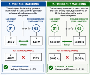
- Voltage Matching: Adjusting the generator’s output voltage to match the grid or reference generator.
- Frequency Matching: Aligning the generator’s frequency with that of the grid or another generator using speed control mechanisms.
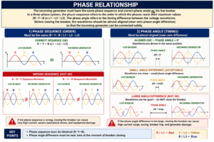
- Phase Synchronization: Adjusting the phase angle to ensure it matches, often utilizing synchronizing devices like relays or synchroscopes.
- Circuit Breaker Closure: Once alignment in voltage, frequency, and phase is achieved, the generator is connected to the grid or other generators, beginning its power supply.
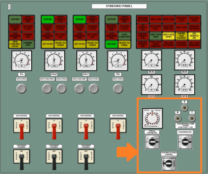
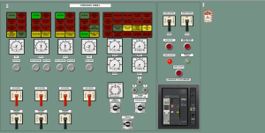
The above image, titled “Synchro Panel,” shows the control interface for managing generators on a ship. It includes various gauges, meters, and controls that are essential for monitoring and managing electrical power generation. Some key features of the synchro panel include:
- ACB (Air Circuit Breaker) Control Switches: These are used to open and close the circuit breakers, which control the flow of electricity from the generators.
- Generator Control and Monitoring: The gauges indicate important parameters such as kilowatts (kW), which measure power output, and other gauges for monitoring voltage and frequency.
- Auto Synchronizing and Load Sharing: Knobs and controls for auto synchronizing the generators and shifting load between them to ensure balanced power distribution and efficient operation.
- Engine Control: There are switches for starting and stopping the diesel generators (DG1 and DG2), along with emergency controls and indicators for electrical faults.
Load Sharing and Its Significance
Beyond the mechanical act of synchronization, the principle of load sharing holds equal significance, ensuring that the electrical burden is equitably distributed amongst the generators. This not only optimizes their usage, preventing individual generator overload, but also bolsters fuel efficiency and bolsters operational dependability. Load sharing brings with it the added advantage of redundancy, permitting other generators to compensate smoothly and maintain continuity in the event of a generator outage.
Load sharing encompasses measuring the load on each generator and adjusting their output to achieve an even distribution. This involves:
- Load Measurement and Adjustment: Using sensors to monitor load and controllers to adjust the generator’s output accordingly.
- Continuous Monitoring: Keeping track of the load distribution in real-time and making necessary adjustments to maintain the desired balance.
Consequences of Poor Synchronization:
- Voltage Imbalance: If voltage levels are not matched, it can cause the generators to overload or produce uneven power distribution, damaging equipment.
- Frequency Difference: If frequencies are not aligned, it can result in mechanical stress on the generators and connected machinery.
- Phase Mismatch: A phase angle mismatch can cause large electrical currents to surge through the system, damaging both the generators and electrical components.
In summary, generator synchronization on ships is essential for maintaining the stability of the electrical system, ensuring safety, and preventing equipment damage. Proper training and careful execution of this procedure are critical for marine engineers and crew.
The synchronization and load sharing of generators on ships are crucial for ensuring efficient, reliable, and safe electrical power supply. These processes not only optimize generator use but also enhance the overall stability of the ship’s electrical system, contributing significantly to the seamless operation of maritime vessels.
We sincerely appreciate the support of the Engine Room Simulator at the DITEN Department of the University of Genoa (UNIGE) for providing the foundational information and simulator screenshots for this article. Originally developed for educational use within the Maritime Science and Technology program, this article aims to contribute to the advancement of maritime training and knowledge.
This article is prepared thanks to the European Union – NextGenerationEU, under Italy’s Piano Nazionale di Ripresa e Resilienza (PNRR), Missione 4 – Componente 2 – Investimento 1.4 (“Potenziamento strutture di ricerca e creazione di ‘campioni nazionali di R&S’ su alcune Key Enabling Technologies”) fund. Specifically, it was supported by the National Center for Sustainable Mobility (Centro Nazionale per la Mobilità Sostenibile – CNMS), Project Code CN00000023. The MOST (National Center for Sustainable Mobility) project is a key initiative within Italy’s PNRR, focusing on the green and digital transition of the mobility sector, including maritime applications. However, the views and opinions expressed are those of the author(s) only and do not necessarily reflect those of the European Union or the European Commission. Neither the European Union nor the granting authority can be held responsible for them.
By: Dr. R. Karimpour
For more information please also follow below section:
https://www.youtube.com/watch?v=uVTyzsCFE6I
📌 FAQs – Generator Synchronization on Ships
1. What is generator synchronization on ships?
Generator synchronization is the process of matching voltage, frequency, and phase sequence between an incoming generator and the ship’s live power grid (busbar) before connecting them. This prevents electrical faults, equipment damage, and blackouts.
Key steps:
Match frequency (adjust generator speed)
Match voltage (use voltage regulators)
Align phase sequence & angle (via synchroscope or lamps)
Close the circuit breaker once synchronized.
2. Why is synchronization critical?
Proper synchronization ensures:
✅ Stable power distribution (prevents blackouts)
✅ Safe load sharing (avoids generator overload)
✅ Fuel efficiency (optimizes parallel operation)
✅ SOLAS compliance (mandatory under IMO Chapter II-1).
Risks of poor sync:
Mechanical stress on generators
Electrical arcing in switchboards
Power surges damaging sensitive equipment.
3. What are the 4 synchronization conditions?
Voltage match (±1% of grid voltage)
Frequency match (±0.1 Hz of grid frequency)
Phase sequence alignment (identical R-Y-B rotation)
Phase angle sync (near-zero difference at breaker closure).
4. What methods are used for synchronization?
| Method | How It Works | Used On Modern Ships? |
|---|---|---|
| Synchroscope | Rotating needle indicates phase alignment; needle at 12 o’clock = safe to close breaker | ✅ Yes (primary method) |
| Three Dark Lamps | All lamps darken simultaneously when synced | ❌ Rare (backup only) |
| Two Bright, One Dark | Two lamps bright, one dark = correct phase sequence | ❌ Rare (backup only) |
| (Demo: UNIGE Synchroscope Tutorial) |
5. What is generator paralleling?
Paralleling allows multiple generators to share the ship’s electrical load by:
Balancing power output
Improving fuel efficiency
Providing redundancy.
Requirements: Same as synchronization (voltage/frequency/phase alignment).
(Source: DNV GL – Load Sharing Paper)
6. What happens if synchronization fails?
Mechanical damage: Torque stress on generator shafts
Electrical hazards: Arcing, breaker trips, fires
Operational risks: Blackouts, SOLAS violations.
Protocol: Immediately halt cargo operations if sync fails.
7. Auto-sync vs. Manual: Which is better?
| Auto-Synchronization | Manual Synchronization |
|---|---|
| – IMO-preferred – Faster, error-proof – Uses PLCs/relays |
– Backup for emergencies – Requires trained crew – Uses synchroscope/lamps |
| (Source: Wärtsilä Techsim Training) |
–
🔗 References & Further Reading
MarineInsight – How to Synchronize Generators on a Ship?
YouTube – Generator Sync Demo (UNIGE Lab)
Wärtsilä Techsim – Marine power systems
Wikipedia – Blackout Prevention on Ships
IMO SOLAS Ch. II-1 – Generator Safety Standards
Wärtsilä Techsim – Marine Power Systems Training
DNV GL – Load Sharing Technical Paper