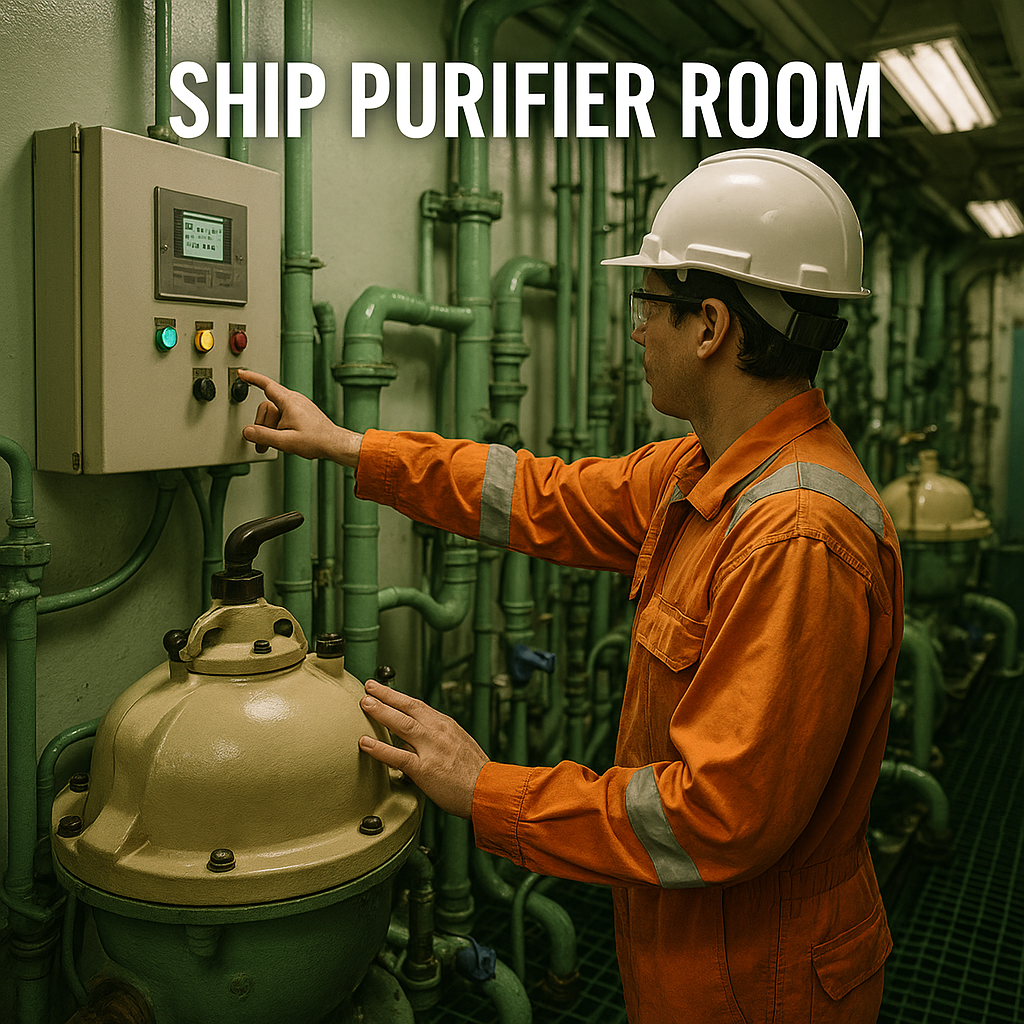
Learn how a ship’s engine room fuel oil system works — from bunkering and purification to fuel delivery and viscosity control. Discover every stage, component, and modern improvement behind the system that keeps main and auxiliary engines running safely and efficiently.
In every large vessel, the engine room is alive with heat, sound, and precision. Deep below deck, fuel oil flows through pipes, valves, and filters — transformed from a thick, dark liquid into a clean, well-conditioned energy source. This is the fuel oil system, a complex network responsible for handling, purifying, and supplying fuel to both the main engine and auxiliary generators.
For maritime professionals, students, and enthusiasts, understanding this system means understanding how ships actually breathe and move. Without it, the world’s merchant fleet would quite literally come to a halt.
Why the Fuel Oil System Matters in Modern Shipping
The fuel oil system ensures that engines receive clean, stable fuel at the right pressure, temperature, and viscosity. These three factors — purity, flow, and consistency — define whether the ship’s engines run efficiently or suffer from damage, delays, and downtime.
Modern fuel systems must also meet strict IMO 2020 sulphur regulations, handle diverse fuels like VLSFO (Very Low Sulphur Fuel Oil) or MGO (Marine Gas Oil), and integrate smart monitoring systems for compliance and energy management. As shipping transitions to greener fuels, this “traditional” system is evolving faster than ever before.
A failure in this system can lead to:
-
Engine stoppage during critical manoeuvres.
-
Excessive wear on injectors, pumps, or cylinders.
-
Non-compliance with MARPOL emission regulations.
-
High maintenance and fuel costs.
Simply put, the fuel oil system is the ship’s internal refinery — the cleaner, the warmer, and the more stable the fuel, the safer and more efficient the voyage.
The Flow of Fuel: From Bunkering to Injection
Every drop of fuel goes through a defined route before reaching the engine injectors:
-
Bunkering and Storage Tanks – Heavy or distillate fuel received from barges or terminals.
-
Settling Tanks – Gravity separation removes water and sludge.
-
Purifiers (Centrifuges) – High-speed cleaning eliminates water and fine solids.
-
Service Tanks – Store purified fuel ready for use.
-
Booster System – Pumps, heaters, filters, and viscosity control deliver conditioned fuel to the engines.
-
Return Flow – Excess warm fuel returns to the mixing column for temperature balance.
Let’s explore each stage and its machinery in depth.
Fuel Oil Settling Tanks
Function: The first line of defence against contaminants. Settling tanks allow fuel to stand quietly so heavier particles and water settle to the bottom.
Each ship usually has two or more settling tanks. While one tank supplies fuel to the purifier, the other is being refilled or cleaned. The tanks are equipped with:
-
Steam heating coils to maintain the temperature (typically 60–70 °C for heavy fuel).
-
Drain valves at the bottom to remove sludge and water.
-
Sounding pipes, temperature sensors, and alarms for monitoring.
Proper operation involves continuous heating, periodic draining, and alternating use to keep water and solids away from downstream components. If neglected, contaminated fuel quickly shortens purifier life and clogs filters.
Fuel Oil Service Tanks
After purification, the fuel is transferred to service tanks, also known as daily service tanks. They contain clean, ready-to-use fuel for the main engine and auxiliary engines.
Ships typically have:
-
Two service tanks for main engine (one in use, one standby).
-
Two for generators or auxiliary engines.
Service tanks are kept at a stable temperature, monitored for contamination, and separated by valves to ensure redundancy. During operation, the fuel supply can be switched instantly if one tank is compromised.
Service tanks are also critical during fuel changeover operations — for example, switching from heavy fuel to low-sulphur MGO when entering Emission Control Areas (ECAs). They must allow gradual blending to prevent sudden viscosity drops or fuel incompatibility.
Fuel Oil Purifiers (Centrifuges)
Fuel purifiers are the heart of the cleaning process. Their task: remove water and solids, especially abrasive cat fines (aluminium and silicon particles left from refinery cracking).
A purifier uses centrifugal force to separate fluids of different densities. Fuel enters the rotating bowl, heavier contaminants move outward, and clean fuel flows inward to the outlet.
Key types:
-
Clarifier: Removes solids only.
-
Separator: Removes both solids and water (most modern ships use this mode).
Typical features:
-
Gravity disc or automatic interface control for maintaining separation layer.
-
Self-cleaning bowl that discharges sludge automatically.
-
Heated fuel inlet (95–98 °C for HFO) to reduce viscosity before separation.
Efficient operation depends on correct temperature, flow rate, and regular maintenance. Failure to operate purifiers correctly can cause cat fines to reach injectors, leading to severe liner and piston wear.
Fuel Transfer Pumps
Transfer pumps move fuel between tanks — from storage to settling, from settling to purifier, and sometimes to service tanks after cleaning.
Design and operation:
-
Usually positive displacement screw pumps with bypass relief valves.
-
Fitted with duplex strainers to remove large debris.
-
Operated automatically or manually depending on system design.
-
Protected by pressure alarms and flow indicators.
Continuous, smooth transfer ensures a stable feed to purifiers. If the pumps cavitate (draw in air) or overheat, the entire fuel preparation chain can be disrupted.
Fuel Booster Pumps
After purification and storage, fuel must be pressurised and delivered to the main engine’s fuel injection system. This is the role of booster pumps, located in the fuel oil booster unit.
These pumps provide steady pressure — usually 7–10 bar — feeding fuel through heaters, filters, viscosity control units, and finally to the engine’s high-pressure pumps or common-rail system.
Modern booster pumps are:
-
Heavy-duty, positive displacement type.
-
Arranged as duty/standby pairs.
-
Controlled automatically for pressure stability.
Any pressure fluctuation can lead to uneven fuel supply, injector malfunction, or loss of power.
Fuel Heaters
Fuel heaters ensure the oil’s viscosity remains within engine manufacturer limits. Heavy fuels can be as thick as tar at ambient temperature; they must be heated before injection.
Types of heaters:
-
Steam heaters (most common).
-
Thermal oil heaters (on ships with thermal systems).
-
Electric heaters (on smaller vessels).
Temperature ranges:
-
Heavy Fuel Oil (HFO): heated to 130–150 °C before injection.
-
Marine Diesel Oil (MDO): typically 40–50 °C.
-
Low Sulphur Fuels: careful control to prevent overheating and instability.
Accurate temperature control prevents thermal shock, poor atomisation, and coking in injectors. Automatic thermostatic valves or viscosity controllers adjust the heating steam to maintain consistent fuel properties.
Fuel Filters (Coarse and Fine)
Filters protect the delicate parts of the fuel system — especially the high-pressure pumps and injectors.
Coarse Filters
Installed upstream of pumps to remove larger particles (>50 μm). These are often duplex strainers that allow cleaning one filter while the other operates.
Fine Filters
Placed before the main engine fuel pumps, typically around 10–25 μm rating. They ensure only clean, contaminant-free fuel reaches the injection system. Differential-pressure gauges show when filters begin to clog.
Regular monitoring and maintenance of filters are critical. Even microscopic particles can score injector nozzles or damage common-rail valves.
Fuel Mixing Column
The mixing column or return fuel mixing unit is a clever piece of design. It mixes hot return fuel from the engine with the cooler supply fuel from the booster system.
This maintains:
-
Stable temperature at engine inlet.
-
Consistent viscosity, avoiding sudden swings during load changes.
-
Reduced heater cycling, improving energy efficiency.
In essence, it’s the thermal buffer of the fuel system. Without it, rapid load variations could cause the fuel temperature to rise or fall too quickly, affecting combustion and viscosity control.
Fuel Flow Meters
Fuel flow meters record the exact consumption of the main and auxiliary engines. These readings are used for:
-
Performance monitoring and fuel efficiency analysis.
-
Emission reporting (EU MRV, IMO DCS, CII compliance).
-
Bunker dispute resolution in commercial operations.
Modern Coriolis mass flow meters measure not only flow rate but also density and temperature, giving accurate mass-based data in real time. They have largely replaced older mechanical or positive displacement meters.
Viscosity Control Unit (VCU)
The viscosity control unit ensures that fuel entering the engine always has the correct viscosity — usually 10–15 cSt at injection point.
How it works:
-
A viscometer measures real-time viscosity.
-
The signal goes to a controller, which regulates the fuel heater.
-
The heater output adjusts automatically to maintain the target viscosity as engine load and fuel properties change.
Stable viscosity means consistent atomisation, combustion, and thermal efficiency. Poor control leads to incomplete combustion, soot formation, or injector fouling.
Modern VCUs use digital sensors and PID control algorithms. They can integrate with engine management systems, automatically adapting when switching between different fuels.
–
Challenges and Modern Developments
The shipping industry is facing a new generation of fuels — low sulphur blends, biofuels, methanol, and even ammonia — all with different handling requirements. Fuel oil systems must adapt to:
-
Unstable VLSFO blends: Some have poor compatibility, leading to sludge formation during changeover.
-
Cat fines and contamination: Require better purification and fine filtration.
-
Automated fuel management: Real-time viscosity, temperature, and flow control through smart systems.
-
Fuel compatibility testing: Ship engineers now perform compatibility tests before mixing bunkers.
-
Integration with data monitoring: Digital flow meters and viscosity controllers feed data to fleet dashboards for analysis.
Manufacturers like Alfa Laval, GEA, Wärtsilä, and Parker Hannifin are continuously improving purifier efficiency, heater control, and automation reliability. These innovations ensure compliance with MARPOL, ISO 8217, and engine-builder standards.
–
Case Study: Modern Purifier and Booster Automation
A new class of LNG-dual-fuel tankers combines automatic fuel management with self-adjusting centrifuges and digital viscosity control. The operator monitors system performance through a single touchscreen interface.
Benefits observed:
-
Reduced manual intervention.
-
Lower energy consumption due to optimised heating cycles.
-
Consistent purifier discharge cycles.
-
Real-time fuel quality data accessible to shore management.
This kind of automation is rapidly becoming standard in newbuilds, supporting both conventional and alternative fuels.
Frequently Asked Questions (FAQ)
Q1: What happens if water enters the fuel oil system?
Water can cause poor combustion, corrosion, and injector damage. It’s removed by settling, purification, and continuous draining.
Q2: How often should fuel purifiers be cleaned?
Self-cleaning types discharge automatically, but bowl cleaning is typically scheduled weekly or after heavy contamination.
Q3: Why do ships use two settling tanks?
One tank is used for supply while the other is settling or being cleaned. This ensures uninterrupted operation.
Q4: Can the same system handle both HFO and MGO?
Yes, but the system must allow gradual temperature and viscosity changeover to prevent thermal shock and asphaltene precipitation.
Q5: What is the ideal viscosity at engine inlet?
Around 10–15 cSt, but always follow the engine manufacturer’s recommendation.
Q6: Why are flow meters important for regulations?
They provide accurate consumption data for IMO DCS, EU MRV, and carbon intensity reporting.
Q7: What is the biggest risk with poor fuel management?
Engine failure due to cat fine damage or unstable fuel mixtures — a risk that modern purification and monitoring systems aim to eliminate.
Conclusion: The Lifeline of Shipboard Power
The fuel oil system is far more than pumps and pipes; it’s a precision chain ensuring that every engine revolution is powered by fuel of the right quality and condition. From the first drop loaded into storage to the final injection pulse inside the cylinder, this system protects the engine, the voyage schedule, and the shipping company’s bottom line.
As global shipping transitions to cleaner fuels, fuel oil systems are evolving into fuel management ecosystems — smart, data-driven, automated, and sustainable. Yet the principles remain timeless: clean fuel, steady flow, proper heat, and constant vigilance.
For cadets and engineers, mastering this system is mastering the language of machinery itself.


