
Step-by-step guide to measuring crankshaft deflection on marine diesel engines in cold condition. Procedure, tools, limits, and troubleshooting explained.
Introduction
The crankshaft is the backbone of a marine diesel engine, converting the reciprocating motion of pistons into rotary motion to drive the propeller. Any bending, misalignment, or uneven loading of this massive component can lead to catastrophic failures — from bearing wipeouts to crankshaft fractures. One of the most reliable diagnostic tools available to engineers is the crankshaft deflection measurement. Taken at regular intervals, usually every 2,000–2,500 running hours or during main bearing overhauls, these measurements reveal the straightness of the crankshaft and the alignment of the engine structure.
The training video Crankshaft Deflection Measurement Procedure (Cold Condition) demonstrates the practical onboard method using a dial gauge and turning gear. In this article, we enrich that content into a comprehensive guide, covering:
- Why crankshaft deflection is critical.
- Tools, setup, and safety precautions.
- Step-by-step cold-state procedure.
- Interpreting results and allowable limits.
- Common causes of abnormal readings.
- Class society and IMO requirements.
- Case studies and digital monitoring trends.
By the end, cadets, engineers, and technical superintendents will understand not only how to perform deflection measurement, but also why it matters for safe and reliable ship operation.
1. Why Measure Crankshaft Deflection?
Crankshaft deflection refers to the bending or flexing of the crankshaft relative to its bearings. It is measured by observing the change in clearance as the crankshaft rotates.
Importance
Crankshaft deflection refers to the bending or flexing of the crankshaft relative to its main bearings, a measurement obtained by observing the change in clearance at different points as the crankshaft rotates. This procedure is of critical importance as it verifies the correct alignment between the crankshaft, its main bearings, and the engine bedplate. By monitoring these measurements over time, engineers can detect abnormal wear in the main bearings long before a catastrophic failure occurs. Ultimately, this practice is essential for preventing a crankshaft fracture, which represents one of the most severe and costly failures in marine engineering. Furthermore, conducting these measurements is not merely a best practice but a formal requirement, as the records must be maintained and presented for class survey reviews.
- Ensures alignment between crankshaft, main bearings, and engine bedplate.
- Detects bearing wear before failure.
- Prevents crankshaft fracture, one of the costliest failures in marine engineering.
- Required for class survey records.
When to Measure
- Every 2,000–2,500 hours of running.
- During main bearing inspection/overhaul.
- After grounding or heavy weather damage.
- If unusual vibrations or bearing temperatures are detected.
2. Tools and Preparations
Tools Required
- Dial gauge/deflection gauge – accuracy up to 0.01 mm.
- Deflection mirror – for visibility in confined spaces.
- Turning gear – to rotate the crankshaft slowly and safely.
- Crankshaft position chart – for recording readings.
Preparations
- Stop the engine and allow it to cool completely (cold-state measurement).
- Open all indicator cocks to prevent pressure build-up.
- Engage the turning gear securely.
- Ensure good lighting inside the crankcase.
3. Step-by-Step Cold-State Deflection Measurement
The video outlines the procedure. Let’s expand each step with details:
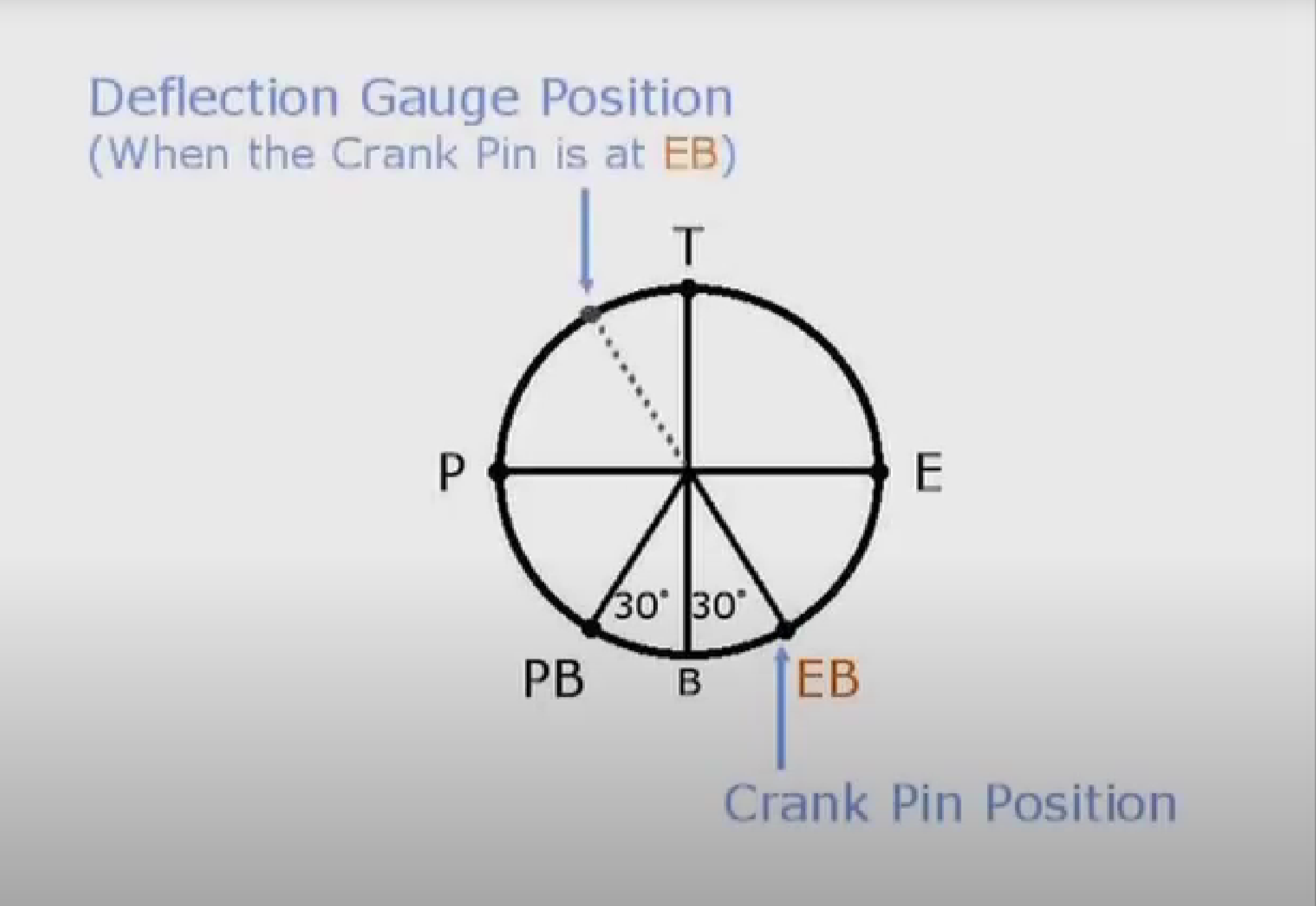
Reference Position – Exhaust Bottom (EB)
- Set crankshaft at Exhaust Bottom (30° after BDC).
- This is the reference position for zeroing the gauge.
Gauge Installation
- Fix dial gauge between crosshead guide (or piston rod) and crank web.
- Ensure gauge is secure and perpendicular.
- Zero the dial reading.
Recording Readings
Rotate flywheel slowly in engine direction, stopping at each position:
- Exhaust Side
- Top Dead Center (TDC)
- Pump Side
- Pump Side Bottom
Record deflections systematically.
Repeat for All Cylinders
- Follow sequence cylinder by cylinder.
- Use deflection mirror if readings are difficult to see.
Log Results
- Enter readings in PMS logbook or electronic system.
- Compare with manufacturer’s allowable values (typically ±0.15 to 0.30 mm depending on engine size).
4. Interpreting Results
The accurate measurement of crankshaft deflection is only the first step; the critical task lies in correctly interpreting the results to diagnose the engine’s condition. Analysis involves comparing the recorded values to the engine manufacturer’s specified limits and, more importantly, identifying the specific pattern or signature of the deflection, as this pattern directly indicates the nature and location of the underlying misalignment or fault within the engine structure.
Normal Pattern
- Readings symmetrical about zero.
- Small deflection within limits.
- No sudden spikes.
Abnormal Patterns
- High top reading → Sagging crankshaft (bearing wear).
- High bottom reading → Hogging crankshaft (bedplate distortion).
- Uneven side readings → Engine misalignment or twisting.
Actions if Out of Limits
- Inspect main bearings.
- Check engine seating and alignment with hull.
- Consult manufacturer and class surveyor.
5. Causes of Excessive Crankshaft Deflection
Excessive crankshaft deflection can be attributed to several key factors. The most common cause is wear of the main bearings, which alters the alignment of the crankshaft support points. Another significant cause is foundation settlement, where the engine’s bedplate becomes misaligned over time due to the constant loads and vibrations of operation. The ship’s hull itself can also be a factor, as hull deflection following heavy weather conditions or a grounding incident can distort the engine’s foundation. Furthermore, uneven thermal expansion must be considered, as measurements taken while the engine is hot may yield different results than those taken in a cold state due to the differential expansion of components. Although rare, manufacturing faults present in new engines remain a possible, albeit infrequent, origin of the problem.
- Main bearing wear (most common).
- Foundation settlement (bedplate misalignment).
- Ship hull deflection (after heavy weather or grounding).
- Uneven thermal expansion (hot-state measurements may vary).
- Manufacturing faults (rare, but possible in new engines).
6. Class Society & IMO Requirements
The importance of monitoring crankshaft deflection is enshrined in international and class regulations. Under the SOLAS (Safety of Life at Sea) Convention, Chapter II-1, ship engines are required to be reliable, and preventive maintenance checks such as deflection measurements form a critical part of compliance. Furthermore, all major classification societies—including DNV, LR, ABS, and BV—mandate that crankshaft deflection measurements are carried out at periodic intervals as an integral component of their survey requirements. This process is often witnessed by a class surveyor during specific surveys, such as those for renewal or in drydock. Complementing this, the STCW Convention mandates that marine engineers possess a fundamental understanding of how to perform deflection checks and interpret their results, establishing this knowledge as a core competency for engine room officers.
7. Case Studies – Lessons from Sea
Case 1 – Early Detection Saved a Voyage
On a container ship, crankshaft deflection exceeded limits in two units. Inspection revealed worn main bearings. Replacing them in port prevented a crankshaft fracture that could have cost millions.
Case 2 – Neglected Deflection Check
A bulk carrier skipped routine checks. Later, the crankshaft broke at the web due to long-term hogging stress. The ship was stranded for 3 months awaiting a new shaft, causing massive delays and chartering penalties.
Case 3 – Hull Stress Influence
After a grounding, a tanker showed abnormal crankshaft deflection. Investigation found hull distortion, requiring engine realignment with hull.
8. Troubleshooting Quick Reference
| Symptom | Likely Cause | Corrective Action |
|---|---|---|
| High readings at top | Bearing wear, sagging | Replace bearings, align engine |
| High readings at bottom | Bedplate distortion, hogging | Realign engine, inspect seating |
| Uneven side readings | Misalignment | Re-level bedplate, inspect hull |
| Sudden changes between cylinders | Local bearing damage | Open up crankcase, inspect unit |
9. Best Practices for Engineers
To ensure accurate and reliable results, engineers must adhere to a set of established best practices when performing crankshaft deflection measurements. It is essential that all measurements are taken with the engine in a cold condition to eliminate any variables introduced by uneven thermal expansion. Prior to starting, the dial gauge must be properly zeroed to establish a correct baseline. Readings should be meticulously recorded in a clear sequence to avoid any confusion during later analysis. Furthermore, engineers should compare new results against the engine’s own trend history, as a gradual change over time can be just as significant as a single reading that exceeds absolute limits. Finally, if any reading is in doubt, the measurement should be repeated to confirm its accuracy before any conclusions are drawn or actions are taken.
- Always measure in cold condition.
- Ensure zeroing of gauge before starting.
- Record readings in sequence (avoid confusion).
- Compare against trend history, not just absolute limits.
- If in doubt, repeat measurement for confirmation.
10. Digital Monitoring & Future Trends
While the traditional method of measuring crankshaft deflection is a manual and labor-intensive procedure, the industry is rapidly evolving towards digitalization and automation. Modern ships are increasingly equipped with advanced technologies such as laser alignment tools and permanent strain gauges integrated directly into the crank webs. This progression is leading to the widespread adoption of Condition-Based Monitoring (CBM) systems, which can automatically and continuously log deflection data. This shift allows for real-time analysis and trend monitoring, moving maintenance away from periodic intervals and towards a more predictive and proactive model, thereby enhancing engine safety and reliability.
Conclusion
Measuring crankshaft deflection in cold condition is one of the most important preventive maintenance tasks for marine diesel engines. It ensures proper alignment, prevents catastrophic crankshaft failures, and maintains compliance with SOLAS, STCW, and class society rules.
The step-by-step procedure demonstrated in the video — and expanded in this guide — shows that with simple tools like a dial gauge and disciplined technique, engineers can safeguard the very backbone of a ship’s propulsion system. When performed consistently and interpreted correctly, deflection measurements not only extend the life of the crankshaft but also protect the ship’s operational reliability and crew safety.
👍