

Crankcase explosions are typically triggered by the presence of a ‘hot spot’ or an overheated component within or near the crankcase of an engine in operation. Under standard operating conditions, the crankcase atmosphere contains oil droplets formed as lubricating oil splashes off bearings onto various moving components. This air-oil mixture is generally non-flammable and will not ignite easily. Lubricating oils used in crankcases are designed with a high closed-cup flash point, usually exceeding 200°C, to minimize explosion risk. The most frequent cause of a reduced flash point is fuel oil contamination.
Localized hot spots may develop due to overheating in areas such as bearings, piston rod glands, or timing chains; they may also result from hot combustion gases or sparks caused by piston blow-by in engines lacking diaphragms, or from adjacent fires—like those in scavenge spaces.
Such hazards can be controlled through diligent maintenance, proper lubrication practices, maintaining oil quality, keeping systems clean, and avoiding engine overload. The widespread use of white metal for bearing surfaces—which softens and melts at moderate temperatures—also helps limit sudden temperature rises.
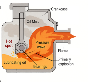
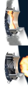
When a hot spot is present, some oil may vaporize upon contact and circulate to cooler areas of the crankcase, where it condenses into a visible white mist composed of finely divided oil particles suspended in air. This mist becomes flammable if it reaches certain concentration levels. If this mist then recirculates back to the original hot spot and remains within the critical concentration range, ignition can occur, resulting in a primary or minor explosion. This minor explosion produces a flame front and a pressure wave that travels through the crankcase, vaporizing additional oil droplets in its path.
If the pressure wave strengthens enough by the time it reaches the crankcase walls, it can potentially blow open crankcase doors or rupture panels—unless pressure is otherwise safely relieved. The following low-pressure vacuum may draw additional air into the crankcase, where it mixes with ignited oil vapors, possibly resulting in a secondary or major explosion. Such an event can inflict extensive damage, ignite fires nearby, and pose serious hazards to personnel.
If hot spot conditions begin to develop, an engine watchkeeper may detect early signs such as irregular engine behavior, abnormal sounds, rising temperatures, unusual smells, or the visible presence of thick white mist within the crankcase.
SAFETY AND OPERATION
Instrumental detection of dangerous conditions may involve temperature-sensitive sensors placed near bearing oil return lines inside the crankcase. More commonly, crankcase mist detectors are employed (see below Figures). These detectors activate visual and audio alarms when mist concentrations are detected—well before reaching explosive thresholds.
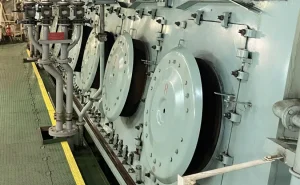
All crankcases, except those on the smallest engines, must be equipped with crankcase explosion relief valves (see below Fig ). These valves open automatically when moderate internal pressures occur, releasing the force from a minor explosion and preventing structural damage. Once the pressure drops, the valves close rapidly, blocking external air from entering and thereby averting the conditions for a major secondary explosion. Relief valves are typically fitted with wire gauze to suppress flame release, and may include deflectors that redirect escaping gases toward safer areas.
Credit: https://www.meoexamz.co.in/2017/11/what-are-requirements-of-crankcase.html
If a hot spot or mist-related alarm is triggered, the engine must be immediately slowed down and shut down as soon as possible to allow the overheating part to cool. During this period, it might be advisable to operate the turning gear while keeping indicator cocks open, preventing any seizure of affected components.
Personnel must stay clear of areas near the relief valves.
It is critical that the crankcase not be opened until sufficient cooling has occurred. Opening it prematurely can admit air and lead to a major explosion. Once the internal parts have cooled adequately, inspections, maintenance, or repairs may safely proceed.
Dividing the crankcase internally can limit flame propagation speed and prevent high-pressure buildup from a primary explosion.
Crankcase access doors should be built to withstand internal pressures and resist rupture. Any internal lighting used in the crankcase must be explosion-proof. Crankcase vent pipes must be of appropriate size—not too large—and should lead to a safe location far from the engine. These vents must include flameproof gauze fittings. Oil drains from the engine must extend below the oil level in the sump to prevent vapor escape. Additionally, the crankcases of separate engines should never be interconnected.
In some installations, inert gas flooding systems may be used to prevent explosions. If employed, the crankcase must be fully ventilated after cooling and before any personnel entry is permitted for inspections.
CRANKCASE OIL MIST DETECTOR
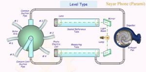
Above Figure presents a schematic of the Graviner oil mist detector, which continuously samples the air-oil vapor mixture from a diesel engine’s crankcase. This device identifies oil mist concentrations well below explosive limits, providing an early warning that allows operators to reduce engine speed and avoid serious damage or explosion.
The detector essentially consists of two parallel tubes of equal dimensions, each housing a photoelectric cell at one end. These cells generate electric current proportional to the intensity of incident light. The tube ends are fitted with filters that allow light transmission. Two identical light beams from a single source are reflected by mirrors and directed along the tubes toward the cells, maintaining electrical balance between them.
One tube contains clean air and serves as the reference tube. The other—called the measuring tube—draws crankcase vapors via an electrically powered extractor fan. When oil mist is present, it partially blocks the light beam reaching the measuring cell, disturbing the electrical balance and activating the alarm system.
Sampling points must be installed on each cylinder’s crankcase, with connections leading to a rotary selector valve driven by the fan motor. This valve sequentially connects each sampling point to the measuring tube. Sampling tubes should be no longer than 12.5 meters and must be sloped for positive oil drainage; they should also be free from loops that could trap oil.
If oil mist is detected, the rotating selector halts to indicate the affected sampling point. The system must be manually reset before the alarm ceases, after which it resumes sampling.
The extractor fan is compact, and tested vapors are discharged to the atmosphere.
Daily functionality tests and sensitivity checks are recommended for the detector. Lenses and mirrors should be cleaned periodically to ensure accurate performance.
In this model, total mist concentration is evaluated relative to clean air. An alternative version draws both the reference and sample streams from crankcase vapors. The reference tube receives a mixture from all crankcases, while the measuring tube sequentially compares this average against individual cylinders and external air. This enables both general and localized detection.
–
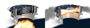
CRANKCASE RELIEF VALVES
Figure below illustrates a typical crankcase explosion relief valve, designed for installation on diesel engine crankcases. This device uses a lightweight, spring-loaded disc valve made of aluminum alloy, which helps reduce inertia and facilitates quick response. A large-diameter spring provides sensitivity and allows the disc to “float” in response to pressure. The absence of a spindle eliminates the risk of valve jamming.
When closed, the valve disc must form a tight seal against gases and oil. A heat-resistant, non-stick rubber ring is fitted to the disc’s face to ensure a secure seal.
Externally, an aluminum valve cap houses the spring and functions as a deflector, channeling any escaping gases in a 120° arc toward the least hazardous area. Inside the crankcase, the valve includes a dome-shaped flame trap made of multiple layers of mild steel wire gauze. This trap becomes coated with oil mist or splashed lubricant, which enhances its heat-dissipating ability and effectiveness in preventing flame spread. The gauze’s free area must be at least equal to the valve’s open area.
The valve is mounted to a crankcase opening using cover studs and spacers, which also serve as guides for the valve disc. The valve spring is calibrated to release at around 5 kN/m² of internal pressure and recloses once pressure is relieved.
Typically, per regulations, diesel engines with cylinder bores greater than 300 mm must be fitted with at least one explosion relief valve of certified design for each crankcase and chain casing. The combined relief valve area should not be less than 115 cm² per cubic meter of crankcase volume. Each valve must have a free area no smaller than 45 cm². Smaller engines are permitted to use fewer and smaller valves. These requirements also apply to large air compressors.
Crankcase doors must be designed to withstand internal pressures until the relief valves can operate.
These valves require minimal maintenance but should be manually tested on a regular basis. The spring mechanism should be inspected, and the flame-trap gauze cleaned periodically.