
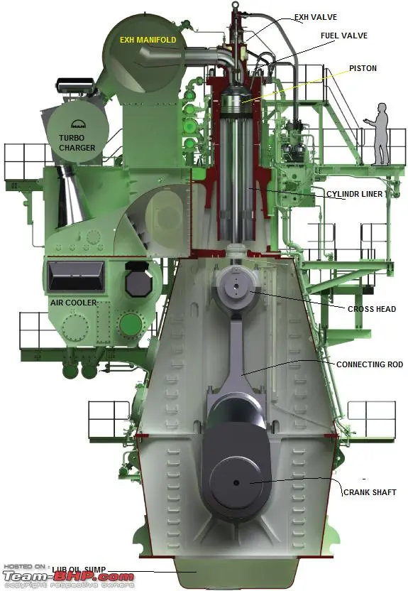
On a ship, a cylinder liner of the main engine is not removed every day. When the job appears in the maintenance plan, it usually means a major overhaul, serious wear, cooling-water leakage, cracking, scuffing, or damage after a piston-ring failure. The liner is large, heavy, and fitted closely inside the cylinder frame. The work therefore needs good preparation, patient handling, and close teamwork.
This article explains the general removal process for a slow-speed MAN B&W MC-C two-stroke marine diesel engine. It is written for learning and job preparation. It does not replace the instruction book for the exact engine type, the ship’s safety management system, the lifting plan, or the Chief Engineer’s instructions. Tool numbers, component arrangements, tightening values, lifting points, and dismantling details can differ between engine bore sizes, mark numbers, builders, and later modifications.
What does the cylinder liner do?
The cylinder liner forms the working surface in which the piston moves. Its inner surface guides the piston rings and helps create a gas-tight combustion space. Scavenge ports in the lower part allow fresh air to enter the cylinder. Cylinder oil is supplied to the liner wall to control friction, wear, corrosion, and deposit formation.
The upper part of the liner is exposed to very high combustion pressure and temperature. Cooling water removes heat from this area. The liner must also transfer mechanical and thermal loads safely to the surrounding engine structure. For these reasons, its condition has a direct effect on compression, lubrication, fuel consumption, reliability, and emissions.
Why may a liner need to be removed?
A liner may be removed for one or more of the following reasons:
- Wear, ovality, or taper has reached the maker’s limit.
- Deep scuffing, scoring, or polishing is present.
- Cracks are suspected or confirmed.
- Cooling water is leaking past sealing rings or through a damaged liner.
- The liner landing surface or cooling space needs repair.
- A broken piston ring has damaged the running surface or scavenge ports.
- Major engine work requires access to the cylinder frame or cooling space.
- The liner is being renewed as part of a planned overhaul.
Before deciding to remove it, engineers should review the cylinder-condition records, liner measurements, piston-ring condition, scavenge-drain data, cylinder-oil performance, and previous defect reports. A liner should not be condemned from one observation alone unless the damage is clearly unsafe.
Safety comes before the spanners
The most important stage begins before any part is loosened.
Hold a toolbox talk and agree on the work sequence. The team should know who is supervising, who controls the crane, who gives lifting signals, and who keeps the work area clear. Discuss the liner’s mass, the crane’s safe working load, the lifting route, the landing position, and what the team will do if the liner does not move normally.
The main engine must be positively prevented from starting or rotating unexpectedly. Follow the ship’s lockout and tagout procedure. Typical precautions include:
- Obtain permission from the bridge and Chief Engineer.
- Stop the engine and allow it to cool to a safe working temperature.
- Shut, lock, and tag the starting-air supply. Vent trapped air where the ship’s procedure requires it.
- Disable remote and local starting arrangements.
- Move the fuel control to the no-fuel position and secure it as required.
- Open the indicator cocks.
- Engage the turning gear and display warning notices at all control positions.
- Isolate and depressurise the relevant cooling-water, fuel, control-air, starting-air, hydraulic, and cylinder-lubrication connections.
- Confirm zero pressure and safe temperature before opening any pipe or cover.
- Protect open crankcase, scavenge-space, oil, air, and water connections against dirt and dropped objects.
Never depend on a control-room switch alone. The isolation must be physical, identified, and checked.
The team should wear the PPE required by the risk assessment. This normally includes a helmet, eye protection, safety shoes, gloves suitable for the task, and hearing protection where necessary. Fall protection may be required on the cylinder top. No person should stand beneath a suspended liner or between the load and a fixed structure.
Tools, equipment, and spares
Prepare everything before opening the engine. A typical job may require:
- The engine-room crane, tested and suitable for the total load.
- The correct OEM liner lifting and tilting tools.
- Certified shackles, slings, chain blocks, and tag lines as specified in the lifting plan.
- Hydraulic tools for studs or nuts, where required by the engine manual.
- The maker’s approved liner extraction or jacking arrangement.
- Cleaning tools, soft scrapers, lint-free cloths, and a vacuum cleaner.
- Measuring tools, including feeler gauges and liner-measuring equipment.
- Protective covers, plugs, labels, trays, and absorbent materials.
- A strong liner stand or prepared wooden supports.
- New O-rings, sealing rings, gaskets, and other planned replacement parts.
- Suitable preservation oil if the liner will be stored.
Check certificates and inspect all lifting equipment. Confirm the tool identification against the instruction manual. Examine lifting screws, threads, shoulders, shackles, and supporting faces for corrosion, wear, cracks, deformation, or earlier misuse. A doubtful lifting tool must not be used.–
–
General removal procedure
1. Record the condition before dismantling
Take useful photographs and record the cylinder number, running hours, defect, recent liner measurements, piston-ring condition, and reason for removal. Mark disconnected parts where this will help correct reassembly. Good records save time later and make the final inspection more meaningful.
2. Prepare the work area and lifting route
Remove or secure platforms, guardrails, deck plates, and nearby pipes only as allowed by the vessel’s procedure. The liner must have a clear vertical path from the cylinder frame. Check the crane’s movement through the full route before attaching the load.
Prepare the landing area in advance. A heavy liner should never be left hanging while the team searches for timber, a stand, or space on the deck.
3. Remove the cylinder cover
Disconnect the pipes, cables, and mechanical connections fitted to the cylinder cover as described in the engine manual. These may include cooling-water pipes, high-pressure fuel pipes, starting-air connections, indicator arrangements, exhaust-valve connections, and monitoring equipment.
Release the cover nuts with the approved hydraulic equipment and in the specified sequence. Fit the correct lifting tool, take the weight evenly, and lift the cover clear. Protect all open pipes and machined faces immediately.
Do not place nuts, tools, or small parts on an unprotected cylinder top. One dropped item can create a much larger repair.
4. Remove the piston and related parts
The piston must normally be removed before the cylinder liner can be lifted. Follow the exact piston-removal procedure for the engine. This work may involve positioning the crank, disconnecting the piston rod from the crosshead, releasing the stuffing box, fitting the piston lifting tool, and lifting the piston and rod through the liner.
Keep the piston stable during the lift and protect the piston rings, piston rod, and liner surface. Land the piston in its prepared stand. Remove the piston cleaning ring, where fitted and where required by the manual.
The piston-removal stage is a separate major operation. Do not shorten it or improvise simply because the liner is the final target.
5. Drain and disconnect the liner services
Confirm that the cylinder cooling-water space is drained and depressurised. Disconnect all services that would prevent movement of the liner. Depending on the particular MC-C arrangement, these may include:
- Cooling-water inlet, outlet, vent, and drain connections.
- Cylinder-lubrication connections or quills.
- Leakage and tell-tale drains.
- Temperature sensors or other monitoring connections.
- Retaining pieces, clamps, studs, or fasteners identified in the manual.
Label small pipes and fittings. Fit clean plugs or covers as soon as each connection is opened. Check the full circumference of the liner. A small pipe left connected can be torn away when the crane takes the load.
6. Clean and inspect the lifting points
Clean the threaded lifting holes and their spot-faces carefully. Remove carbon, dirt, paint, rust, and preservation compound without damaging the threads or machined faces. Make sure the lifting screws can be fitted by hand for the correct thread engagement.
This is a critical MAN safety point. MAN Service Letter SL2012-566, applicable to 35-98 bore MC/MC-C and ME/ME-C engines, instructs operators to make sure there is full contact between the lifting screw shoulder and the machined spot-face on the liner. The contact should be checked visually or with a feeler gauge before lifting.
If the shoulder does not sit fully on the liner, or the thread engagement appears insufficient, stop the job. Do not solve the problem by adding random washers, forcing the screw, or making an unapproved alteration. Check the exact engine documentation and obtain advice from the maker or an authorised service representative.
7. Attach the crane and make a trial lift
Connect the crane to the approved lifting arrangement. The pull must be vertical and balanced. Use tag lines where they improve control without putting a person in the danger zone.
Take up the slack slowly. Pause when the lifting gear is just under tension. Check that:
- Both lifting points carry the load evenly.
- The lifting screws remain fully seated.
- Shackles and slings are correctly aligned.
- Nothing is still connected to the liner.
- The crane wire is vertical.
- All personnel are clear.
This short pause is one of the best opportunities to catch a mistake before it becomes an accident.
8. Release the liner from its seating
After years of service, the liner may be held by deposits, corrosion, old sealing rings, or a tight fit. Use only the maker’s approved extraction or jacking method. Apply the force evenly and watch the liner at several points around its circumference.
Do not use the lifting screws as pry bars. Do not strike machined sealing faces with a steel hammer. Do not pull the liner sideways with the crane.
A common moment in this job is when the liner rises a few millimetres and then stops. That is the time for patience. Lower or hold the load safely, find the obstruction, and correct it. More crane force is not a diagnosis.
9. Lift the liner vertically
Once the liner is free, raise it slowly. A designated signal person should guide the crane operator. Watch the liner continuously as the lower part and scavenge ports pass through the cylinder frame.
Keep hands away from pinch points. Use tag lines rather than pushing directly against a swinging load. Stop immediately if the liner tilts, catches, rotates unexpectedly, or causes the crane load indicator to behave abnormally.
If the liner must be tilted for transport or landing, use the approved tilting tool and the maker’s load-transfer sequence. The centre of gravity changes quickly during tilting. Never improvise with a loose chain or an unapproved hole.
10. Land and secure the liner
Lower the liner onto its prepared stand or supports. Make sure it cannot roll, tip, or damage the lower edge, sealing grooves, or running surface. Remove the lifting gear only after the liner is stable.
If the liner will be sent ashore, prepare a lifting and transport frame suitable for the liner’s size and mass. Protect all machined surfaces against impact, dirt, and corrosion.

–
What should be inspected after removal?
Removal gives access to areas that are normally hidden. Use the opportunity well.
The cylinder liner
Clean the liner sufficiently for inspection. Look for scuffing, deep scores, cracks, corrosion, cavitation, polishing, abnormal wear near the top, blocked lubricating holes, and damage around the scavenge ports. Examine the outer cooling surface and all sealing grooves.
Measure the bore at the positions and directions stated in the engine manual. Record the readings, not only the final conclusion. Calculate wear, ovality, and taper using the maker’s method and compare them with the correct limits for that engine.
If crack detection, pressure testing, honing, wave cutting, or machining is required, it should be performed by competent personnel using an approved procedure.
The cylinder frame and cooling space
Inspect the liner landing surface, cooling-water space, sealing areas, and nearby frame structure. Look for corrosion, erosion, cracks, fretting, deposits, and signs of water leakage. Clean drains and confirm that tell-tale passages are open.
Cover the cylinder opening when inspection is not in progress. A clean overhaul can be ruined by one nut falling into the scavenge space.
Related components
The removed liner should not be examined alone. Review the piston crown, rings, ring grooves, piston skirt, stuffing box, cylinder-oil quills, piston cleaning ring, and scavenge drains. The pattern of damage often tells a story. For example, liner scoring may be connected to broken rings, poor oil distribution, abrasive particles, water entry, or incorrect running conditions.
–
Common mistakes and how to avoid them
| Common mistake | Better practice |
|---|---|
| Starting before the lifting route and landing place are ready | Plan the full movement of the liner before dismantling begins. |
| Treating electrical isolation as sufficient | Apply the ship’s complete mechanical and electrical lockout procedure. |
| Fitting lifting screws into dirty holes | Clean and inspect the threads and spot-faces before fitting the tools. |
| Looking only at thread engagement | Also confirm full shoulder contact with the liner spot-face. |
| Pulling harder when the liner sticks | Stop, identify the obstruction, and use the approved extraction method. |
| Allowing a side pull on the lifting tools | Keep the crane wire vertical and the load balanced. |
| Leaving one drain, sensor, or small pipe connected | Check the full circumference before taking the load. |
| Working beneath or beside an uncontrolled suspended load | Establish an exclusion zone and use tag lines from a safe position. |
| Landing the liner on an unprepared deck | Use a stable stand that protects machined and sealing surfaces. |
| Relying on memory for clearances or limits | Use the instruction book and record actual measurements. |
–
Advice for cadets and engineers
For a cadet, this job is a valuable lesson in more than dismantling. Watch how the senior engineers prepare the work. Notice how pipes are labelled, parts are arranged, lifting signals are agreed, and measurements are recorded.
Ask useful questions before the lift, not while the liner is hanging. Learn the name and purpose of each special tool. Compare the real engine with the drawings in the instruction book. Most importantly, understand that stopping a job when something looks wrong is good engineering, not hesitation.
Do not try to prove yourself by standing close to the load or taking an unsafe shortcut. A good engineer is not the person who finishes first. A good engineer finishes safely, protects the machinery, and leaves clear records for the next watch.
–
Short job checklist
Before lifting the liner, confirm:
- Work permit, risk assessment, toolbox talk, and lifting plan completed.
- Bridge and engine-control positions informed.
- Starting air isolated, locked, and depressurised as required.
- Turning gear engaged and remote starting disabled.
- Indicator cocks open and engine at a safe temperature.
- Relevant fluids isolated, drained, and at zero pressure.
- Cylinder cover and piston removed by the correct procedures.
- All liner services, sensors, drains, and retaining parts disconnected.
- Correct lifting tools identified, inspected, and fitted.
- Full lifting-screw shoulder contact confirmed visually or by feeler gauge.
- Crane, slings, shackles, tag lines, and liner stand ready.
- Lift is vertical, balanced, and controlled by one signal person.
- Exclusion zone established and no person below the load.
- Open engine spaces and connections protected from contamination.
–
Final thought
Removing a cylinder liner is heavy work, but success depends more on control than strength. The safest team is usually the team that prepares carefully, lifts slowly, communicates clearly, and stops when the machinery does not behave as expected.
On a MAN B&W MC-C engine, never treat the liner as just another heavy component. It is a precision engine part, and the tools that lift it are part of the safety system. Clean contact faces, correct tool engagement, a vertical lift, and respect for the maker’s procedure are what turn a difficult overhaul into a professional job.
–
References and further reading
- MAN Diesel & Turbo, Service Letter SL2012-566/PRP: Lifting of Cylinder Liner—35-98 bore engines, applicable to MAN B&W MC/MC-C and ME/ME-C two-stroke engines: https://www.man-es.com/docs/default-source/service-letters/sl2012-566.pdf
- MAN Energy Solutions / Everllence, Two-stroke Service Letters—Table of Contents, including liner lifting, condition, inspection, and safety notices: https://www.everllence.com/docs/default-source/service-letters/table-of-content/2-stroke-table-of-content.pdf
- MAN Diesel, Service Letter SL2009-521/NJC: Inspection Inside Cylinder Liners, including basic safety references for work involving cylinder access: https://www.man-es.com/docs/default-source/service-letters/sl2009-521.pdf
- The vessel-specific MAN B&W MC-C Operation Manual, Maintenance Manual, engine-room crane instructions, special-tool catalogue, and shipboard Safety Management System. Always use the latest controlled copies carried on board.
Read more articles here:
MAN B&W Two-Stroke Slow-Speed Diesel Engines: Evolution in Marine Propulsion
Basics of Marine Diesel Engine Generators: A Practical Guide
How to Measure Crankshaft Deflection | Cold-State Procedure for Marine Diesel Engines