
Learn where the emergency bilge suction valve is located on ships, why it matters in flooding emergencies, and how maritime regulations govern its design and use.
When a ship begins to flood, minutes can mean the difference between a controlled emergency and a total loss. Water entering the hull does not politely wait for orders; it spreads quickly, seeking the lowest spaces and the weakest boundaries. For this reason, ships are equipped with a special line of defense known as the emergency bilge suction valve. Unlike the normal bilge system, which works like a well-organised drainage network, this emergency arrangement is closer to a fire hose: simple, powerful, and ready to move large volumes of water fast.
Yet many cadets, junior engineers, and even experienced seafarers still ask a deceptively simple question: Where exactly is the emergency bilge suction valve located on a ship? The answer is not just about geography. It is about safety philosophy, regulatory design, and real-life survival at sea.
Understanding the physical location of this valve, and the reasoning behind it, is not academic curiosity. It is operational knowledge that can save ships, cargo, and lives.
Why This Topic Matters for Maritime Operations
Flooding remains one of the most dangerous emergencies at sea. According to casualty investigations by bodies such as the UK Marine Accident Investigation Branch (MAIB) and the United States Coast Guard (USCG), progressive flooding is a leading cause of engine room loss and vessel abandonment. The emergency bilge suction valve exists specifically for situations where the normal bilge system becomes overwhelmed or inoperative.
Knowing its location is therefore not a luxury; it is part of professional competence. In an emergency, crews do not have time to search manuals or follow signs slowly. They must move directly to the correct valve, often in darkness, heat, noise, and stress.
Understanding the Emergency Bilge Suction System
What Is an Emergency Bilge Suction Valve?
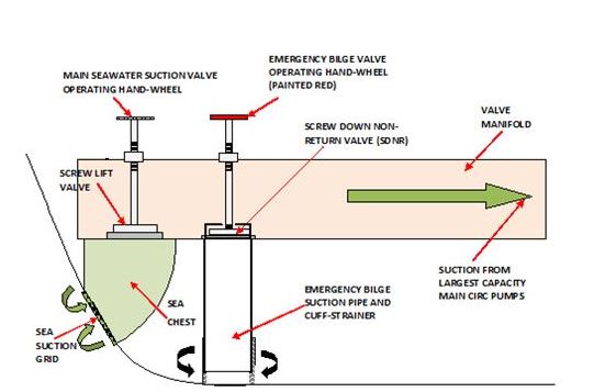
In simple terms, the emergency bilge suction valve is a direct connection between the bilge space and a high-capacity pump, usually the main seawater cooling pump or ballast pump. Under normal conditions, bilge water passes through strainers, non-return valves, and separators. In an emergency, those restrictions may reduce pumping efficiency or clog completely. The emergency suction bypasses much of that complexity.
This arrangement is required under international rules such as the International Convention for the Safety of Life at Sea (SOLAS), specifically Chapter II-1, which governs machinery and bilge pumping arrangements. Guidance is provided by the International Maritime Organization (IMO) and implemented by classification societies such as DNV, Lloyd’s Register, and ABS.
Why Location Matters
A valve that cannot be reached is useless. If it is hidden behind hot machinery, obstructed by cargo, or placed too high above the bilge well, it loses its emergency function. The location is therefore dictated by three principles: accessibility, directness, and survivability.
Accessibility ensures crew can operate it quickly. Directness ensures minimal pipe length and minimal flow loss. Survivability ensures it remains usable even when parts of the engine room are compromised.
Where the Emergency Bilge Suction Valve Is Located on Ships
The Typical Location: Engine Room Bilge Well Area
On most cargo ships, tankers, and passenger vessels, the emergency bilge suction valve is located in the engine room, close to the main bilge well and directly connected to a main seawater cooling pump or ballast pump suction line.
This means that physically, the valve is usually found:
-
Near the bilge well in the engine room, often at the lowest deck level
-
On or adjacent to the main seawater pump suction line
-
Within manual operating reach, without tools
-
Marked clearly as “Emergency Bilge Suction”
Imagine the bilge well as a floor drain in a building. The emergency suction is like connecting a fire pump directly to that drain, bypassing the normal plumbing. For this to work, the valve must be close to both the drain and the pump.
On large merchant ships, this valve is often installed on a branch line off the seawater suction manifold, with a clearly labelled handwheel or lever. The piping arrangement is intentionally simple to reduce the chance of failure.
Variations by Ship Type
The exact location varies with ship design, but the principle remains constant.
On container ships and bulk carriers, the valve is usually mounted low on the engine room bilge line, often between the bilge well and the pump suction manifold. Designers favour this position because these ships have large engine rooms with multiple bilge wells.
On oil tankers and chemical tankers, additional safety measures apply due to fire and explosion risks. Here, the emergency bilge suction valve is still in the engine room but may be fitted with extra isolation valves and flame-resistant materials, following guidance from classification societies such as Bureau Veritas and RINA.
On passenger ships and cruise vessels, redundancy is higher. The emergency suction may be duplicated or integrated into advanced bilge automation systems, but a manual emergency valve is still required by regulation. Its location is typically in the engine control area or near the lowest bilge space, with remote indicators on the bridge.
On smaller vessels, including offshore supply vessels and fishing vessels, the emergency bilge suction may be combined with the fire pump suction line. In these cases, the valve is often located close to the pump itself rather than the bilge well, but it still connects directly to the lowest compartment.
Regulatory Perspective on Location
SOLAS does not prescribe an exact coordinate for the valve. Instead, it sets functional requirements: the emergency bilge suction must be capable of drawing water from the main machinery space bilge and must be operable locally. Classification societies interpret this into design rules.
For example, DNV’s Rules for Ships specify that the emergency bilge suction must be arranged so that it can be operated without entering dangerous spaces if possible. Lloyd’s Register requires clear marking and accessibility. ABS emphasises separation from normal bilge valves to avoid confusion during emergencies.
In practical terms, this means the valve is almost always:
-
In the engine room
-
Near the bilge wells
-
On a direct line to a high-capacity pump
-
Clearly labelled and distinct from normal bilge valves
Design Principles Behind the Location
Simplicity Over Sophistication
In emergencies, complex systems fail first. Designers therefore locate the emergency bilge suction valve where it requires the least number of intermediate components. Short pipe runs mean less resistance and fewer potential leak points. This is why the valve is physically close to the pump suction line and the bilge well.
This design mirrors firefighting systems. Just as a fire main is connected directly to pumps without unnecessary detours, the emergency bilge suction follows the same philosophy. The shorter the path, the faster the water moves.
Human Factors and Ergonomics
Engineers operate under stress during flooding. Heat, steam, alarms, and noise reduce visibility and concentration. A valve located behind machinery or above head height increases the chance of error. Modern ship designs, guided by human factors research from institutions such as the International Maritime Organization and the [International Maritime Organization’s Human Element Committee], therefore place the valve in a clear walkway area, often near other emergency controls.
Some ships also include photoluminescent markings or reflective labels to make the valve visible during power loss. This practice is recommended in safety management guidance by the International Chamber of Shipping (ICS).
Survivability in Flooding Scenarios
If flooding starts at the bottom of the engine room, the valve must not be submerged too quickly. Designers therefore place it slightly above the bilge well but still close enough for direct suction. This balance ensures that the valve can be operated before water rises to dangerous levels.
Practical Operation in Real Emergencies
A Real-World Example: Machinery Space Flooding
In 2017, a general cargo ship in the North Sea suffered a seawater ingress through a fractured cooling line. The normal bilge system could not cope with the inflow. According to investigation summaries published by the MAIB, the engine room team opened the emergency bilge suction valve and connected the main seawater pump directly to the bilge. This action stabilised the flooding long enough to isolate the leak and prevent loss of propulsion.
The crew knew exactly where the valve was located because it had been included in drills. Their success did not depend on technology alone but on familiarity with physical layout.
Interaction with Other Systems
When the emergency bilge suction is opened, it usually overrides normal bilge suction. This means the pump draws from the bilge instead of the sea. Engineers must therefore monitor pump temperature and discharge pressure closely. Drawing debris-laden water can damage impellers if not controlled carefully.
This interaction highlights why the valve is placed near pump controls. Proximity allows one person to operate both systems without moving across the engine room, which is especially important during blackouts or fire scenarios.
Challenges and Practical Solutions
A common challenge is that emergency bilge suction valves are rarely used in normal operation. Over time, they can become stiff, corroded, or partially seized. Investigations by classification societies such as ClassNK and DNV repeatedly show that emergency valves sometimes fail during surveys due to lack of exercise.
The practical solution is procedural rather than technological. Ships are required under the International Safety Management (ISM) Code to test emergency systems regularly. This includes verifying the valve’s movement, checking for leaks, and confirming that the connected pump can develop sufficient suction.
Another challenge is confusion with other bilge valves. In some older ships, valve wheels look identical, and labels fade. Modern practice is to use distinctive colours or shapes for emergency valves, reducing the risk of operating the wrong control. This approach aligns with guidance from the International Association of Classification Societies (IACS).
Case Studies and Real-World Applications
Cruise Ship Flooding Prevention
On a large cruise ship operating in the Mediterranean, a fractured pipe caused rapid bilge rise in the auxiliary engine room. The emergency bilge suction valve was located on the lower platform near the bilge well, connected to a dedicated ballast pump. According to safety bulletins from the European Maritime Safety Agency (EMSA), the crew activated the emergency suction and transferred water to a holding tank, preventing passenger disruption and avoiding port diversion.
This case demonstrates how location supports rapid response. If the valve had been placed several decks above, the delay might have resulted in electrical failures.
Tanker Engine Room Incident
In a tanker incident reviewed by BIMCO safety forums, a loose sea chest valve allowed seawater to flood the engine room. The emergency bilge suction valve, located adjacent to the main seawater pump suction manifold, allowed immediate diversion of pumping capacity to the bilge. The crew isolated the sea chest and restored stability.
In both cases, the success factor was not innovation but correct placement and crew familiarity.
Future Outlook and Maritime Trends
Ship systems are becoming more automated, with smart bilge alarms and remote valve controls. Some modern vessels integrate emergency bilge suction into digital monitoring platforms, allowing bridge teams to see bilge levels and pump status in real time. Companies such as Wärtsilä and Alfa Laval are developing integrated bilge management systems that improve response times and reduce human error.
However, regulatory bodies remain cautious about removing manual controls. The IMO and classification societies continue to require physical emergency bilge suction valves, even on highly automated ships. The philosophy is clear: electronics can fail, but a steel valve operated by human muscle remains reliable.
Future trends may refine valve materials, improve corrosion resistance, and enhance visibility, but the fundamental location principle is unlikely to change. The emergency bilge suction valve will remain in the engine room, close to the bilge well and pump suction line, because physics and human factors still demand it.
FAQ Section
1. What is the main purpose of an emergency bilge suction valve?
Its purpose is to allow a high-capacity pump to draw water directly from the bilge in flooding emergencies, bypassing the normal bilge system.
2. Where is the emergency bilge suction valve usually located?
It is usually located in the engine room, near the bilge well and on the suction line of a main seawater or ballast pump.
3. Is the location fixed by SOLAS?
SOLAS defines the function, not the exact position. Classification societies translate this into practical design rules that result in similar locations across ship types.
4. Can the fire pump be used as an emergency bilge pump?
On some ships, yes. The emergency bilge suction valve may connect the fire pump suction to the bilge, depending on the ship’s design and class rules.
5. Why is it not placed on the bridge?
Because it must connect physically to the bilge and pump suction line. Remote controls may exist, but the main valve is located near the machinery for reliability.
6. How often should the emergency bilge suction valve be tested?
It should be tested regularly as part of ISM procedures and during class surveys, usually monthly or during routine machinery drills.
7. What happens if the valve is submerged during flooding?
It may become inaccessible, which is why it is placed slightly above the bilge well level and clearly marked for rapid operation.
Conclusion / Take-Away
The emergency bilge suction valve is one of the most critical yet overlooked components of a ship’s safety system. Its location is not random. It is placed in the engine room, close to the bilge well and connected directly to a high-capacity pump, because this position offers the fastest and most reliable way to remove water during flooding emergencies.
This design reflects decades of maritime experience, regulatory oversight, and accident investigation. From cargo ships to cruise liners, the principle remains the same: short pipes, clear access, and human operability.
For seafarers, the lesson is simple but powerful. Know where the emergency bilge suction valve is on your ship. Walk to it. Touch it. Include it in drills. In a real emergency, knowledge of that single valve may determine whether your ship survives or sinks.
References
International Maritime Organization (IMO). (2023). SOLAS Chapter II-1: Construction – Structure, Subdivision and Stability, Machinery and Electrical Installations. https://www.imo.org
International Association of Classification Societies (IACS). (2022). Unified Requirements on Bilge Systems. https://iacs.org.uk
Lloyd’s Register. (2023). Rules and Regulations for the Classification of Ships. https://www.lr.org
DNV. (2024). Rules for Ships – Machinery and Systems. https://www.dnv.com
American Bureau of Shipping (ABS). (2023). Marine Vessel Rules – Bilge and Ballast Systems. https://ww2.eagle.org
European Maritime Safety Agency (EMSA). (2023). Annual Overview of Marine Casualties and Incidents. https://www.emsa.europa.eu
Marine Accident Investigation Branch (MAIB). (2022). Safety Digest and Flooding Case Reviews. https://www.gov.uk/maib
BIMCO. (2023). Machinery Space Safety Guidance. https://www.bimco.org
Wärtsilä. (2024). Integrated Bilge and Ballast Solutions. https://www.wartsila.com
Alfa Laval. (2024). Bilge Water Management Systems. https://www.alfalaval.com