
Explore how ship compressed air systems power critical operations — from engine starting to automation control and general service air. This in-depth guide explains compressors, air bottles, dryers, and safety valves with real-world examples, humanised language, and modern engineering insights.
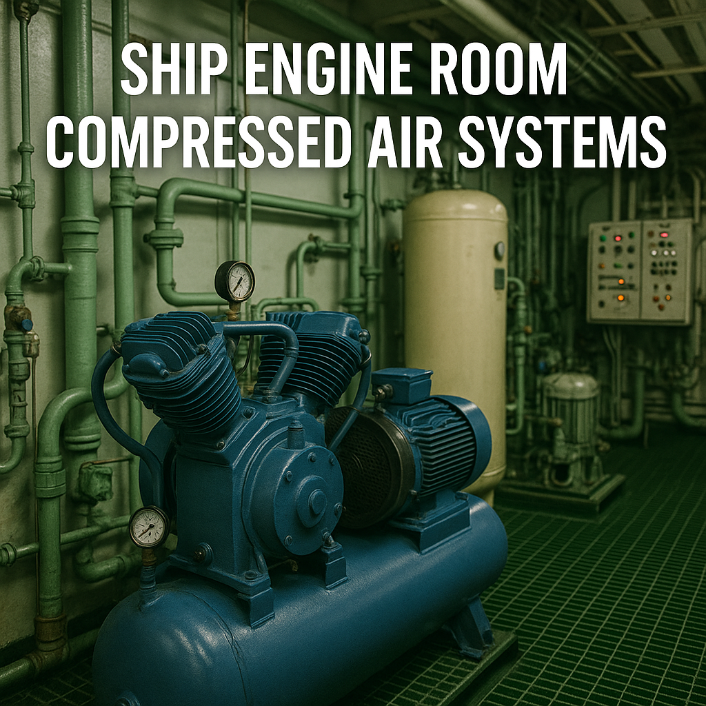
Walk into a ship’s engine room, and you’ll hear a constant rhythmic hum — pumps, motors, fans, and compressors working together like lungs in a living body. Among them, one system quietly supports nearly every operation onboard: the compressed air system.
Whether it’s starting a main engine, operating pneumatic valves, powering control systems, or simply cleaning machinery, compressed air is indispensable. Without it, a ship cannot start, maneuver, or even function safely.
This article offers an in-depth, humanised, and technically sound explanation of the ship’s compressed air system, its components, working principles, maintenance, and future innovations — written for maritime students, professionals, and enthusiasts worldwide.

Why Compressed Air Systems Matter in Maritime Operations
Air, when compressed and stored under pressure, becomes a potent source of mechanical energy. On ships, this energy does far more than inflate tyres or power tools — it starts massive two-stroke diesel engines, controls automation systems, and keeps operations safe and efficient.
A typical ocean-going vessel uses compressed air for:
-
Main engine starting (using high-pressure air directly to cylinders).
-
Generator engine starting (smaller receivers or direct electric start).
-
Control air (operating automation valves, pneumatic relays, and control panels).
-
Service air (for general cleaning, maintenance, whistles, or instrumentation).
Compressed air is sometimes called the ship’s “invisible power.” It’s clean, reliable, and available instantly. But achieving that reliability demands a well-designed network of compressors, receivers, dryers, valves, and safety devices — all monitored carefully for leaks, oil carryover, or pressure drops.
Understanding the Layout of the Ship’s Compressed Air System
At its core, a ship’s compressed air system includes:
-
Main Air Compressors – Generate and store high-pressure air for main engine starting.
-
Starting Air Bottles (Receivers) – Store air safely until used.
-
Control Air Compressors – Supply lower-pressure air for automation and control.
-
Service Air Compressors – Provide general-purpose air for cleaning and shipboard services.
-
Air Dryer Unit – Removes moisture to prevent corrosion and freezing.
-
Pressure Reducing Valves (PRVs) – Adjust and stabilise air pressure for different subsystems.
-
Safety Valves and Air Manifolds – Protect the system and distribute air efficiently.
Together, these components form an intricate system that balances high-pressure reliability with low-pressure flexibility.
Main Air Compressors: The Powerhouse of Starting Air
Purpose
Main air compressors are the heart of the system. They compress ambient air (from around 1 bar atmospheric pressure to roughly 30 bar) and feed it into the starting air bottles. This air later provides the massive burst of energy needed to start the main engine.
Construction and Operation
Most shipboard compressors are two-stage, water-cooled, reciprocating units designed for continuous and automatic operation.
-
First Stage: Air is drawn in, compressed to around 5–6 bar, and cooled in an intercooler.
-
Second Stage: The partially cooled air is compressed again to 30 bar, cooled in an aftercooler, and discharged to the receiver.
-
Cooling and lubrication are vital to avoid overheating and wear.
Each compressor is typically fitted with:
-
Automatic start/stop controls (maintaining bottle pressure between 25 and 30 bar).
-
Safety valves to prevent overpressure.
-
Non-return valves preventing backflow from the air bottles.
-
Moisture traps and air filters to remove condensation and dust.
Ships usually have two main air compressors — one duty and one standby — ensuring redundancy. In case of one compressor failure, the other can maintain operational readiness.
Maintenance Insight
Engineers regularly check oil levels, valve conditions, discharge temperatures, and vibration. Overheating or oil carryover are warning signs — both can cause dangerous air-line fires.
Starting Air Bottles (Air Receivers)
Function and Role
The compressed air generated by the main compressors is stored in starting air bottles — massive, cylindrical pressure vessels typically made of steel. Each receiver holds high-pressure air (around 30 bar) ready to be released for engine starting.
Design Features
-
Each bottle has a safety valve, pressure gauge, drain valve, and non-return valve.
-
Receivers are designed according to class rules (DNV, ABS, Lloyd’s Register, etc.) and undergo periodic testing for pressure integrity.
-
Capacity requirements are defined by IMO and classification societies — enough to start the main engine at least 12 times (if reversible) or 6 times (if non-reversible).
Starting Sequence
When the bridge or engine control room gives a start command:
-
Air flows from the bottle through a main starting valve.
-
Distributed to individual cylinders via a starting air manifold.
-
Air enters selected cylinders in sequence, turning the engine until fuel ignition takes over.
Once the engine starts, the compressor automatically recharges the bottles to full pressure.
Control Air Compressors
Function
While main air operates at 30 bar, control air systems require only 6–8 bar pressure — suitable for operating automation systems, pneumatic control valves, alarms, and remote operation systems.
Control air compressors are smaller, oil-free units, ensuring clean, dry air for sensitive instruments. Oil or moisture contamination can cause pneumatic control failures, leading to unsafe operations.
Components and Design
-
Single or two-stage air compressors, often with built-in aftercoolers.
-
Moisture separators and filters to ensure air purity.
-
Connected to a control air receiver via a pressure-reducing valve.
-
Sometimes combined with service air systems, with filters separating each line.
Clean, stable air ensures precise control of automation systems — from exhaust valves to remote fuel shutoffs.
Service Air Compressors
Purpose
The service air system provides compressed air for general shipboard purposes such as:
-
Cleaning engine room machinery and filters.
-
Operating pneumatic tools (grinders, drills, paint guns).
-
Blowing through pipes or purging tanks.
-
Operating the ship’s whistle or horns.
Service air compressors generally deliver air at 7–8 bar and are equipped with dryers, filters, and automatic moisture drains.
Operational Integration
In many modern vessels, the service and control air systems are interconnected with dedicated regulators and filters to prevent contamination. Redundancy is achieved by having at least two compressors — one in use, one standby.
Air Dryer: Keeping the System Dry and Healthy
Why Dry Air Matters
When air is compressed, its temperature rises — and as it cools, moisture condenses. Without drying, this water would corrode pipelines, freeze in valves, and damage instruments.
Types of Air Dryers
-
Refrigeration Dryers: Cool the air to around 3°C to condense and remove moisture.
-
Desiccant Dryers: Pass air through a chemical drying agent like silica gel or activated alumina.
-
Combination Units: Use both methods for redundancy and higher efficiency.
Operation
The air dryer is typically placed after the service/control compressors and before the receiver. It removes up to 99% of water vapour, ensuring dew point control below the lowest ambient temperature expected.
Real-World Example
On vessels trading in cold climates, air dryers are vital. Without them, frozen condensate could jam critical pneumatic valves, preventing safe operation of fuel systems or steering gear controls.
Pressure Reducing Valves (PRVs) and Safety Valves
Pressure Reducing Valves
These valves adjust and stabilise air pressure between different subsystems. For example:
-
From 30 bar (main air) down to 7 bar (service/control air).
-
From control air down to 4 bar (instrumentation circuits).
They ensure that each section receives precisely the pressure it needs, avoiding energy waste or equipment damage.
Safety Valves
Every receiver, compressor, and line prone to pressure accumulation has safety valves. They protect the system from overpressure by venting excess air automatically once the set limit is exceeded.
Safety valves are tested during annual and special surveys as per classification rules, ensuring full compliance with SOLAS and IMO standards.
Air Distribution Manifold
The air distribution manifold acts as the “air traffic controller” of the entire system. It routes compressed air to various consumers: starting air lines, control air networks, service outlets, and emergency systems.
Key Features
-
Equipped with isolation valves, pressure gauges, and safety relief valves.
-
Colour-coded lines or tags help engineers identify circuits quickly.
-
Includes drain traps to remove condensate and non-return valves to prevent backflow.
During maintenance, engineers isolate sections of the manifold, drain moisture, and verify that line pressures remain stable under load.
–
Case Study: Main Engine Start on a MAN B&W 6S70ME-C
Let’s visualise the compressed air system in action.
When the bridge issues the “Start” command, the engine control system opens the main starting air valve. Compressed air from two 30-bar receivers flows through the manifold and into specific cylinders.
The engine begins to turn. Within seconds, fuel injection ignites, and the engine starts running on fuel. Once it reaches firing speed, the air supply is cut, and compressors automatically start recharging the receivers.
This process demonstrates how stored energy in air is transformed into mechanical motion, powering a ship that weighs over 100,000 tonnes.
–
Maintenance and Troubleshooting
Proper operation of compressed air systems depends on vigilant maintenance:
-
Drain condensate from receivers and lines daily.
-
Check oil carryover and clean filters regularly.
-
Monitor discharge temperatures — overheating signals valve leaks or piston wear.
-
Inspect safety valves and test set pressures.
-
Ensure dryers operate correctly, especially in cold or humid conditions.
-
Check non-return valves to prevent backflow to compressors.
Common faults include air leakage, water accumulation, sticking valves, or automatic start failure. Routine checks, log entries, and periodic overhauls keep the system reliable.
–
Future Developments and Innovations
Modern vessels are adopting more efficient and environmentally friendly compressed air systems:
-
Variable speed drive (VSD) compressors reduce power consumption.
-
Oil-free screw compressors eliminate contamination risk for sensitive control air.
-
Smart sensors monitor pressure, temperature, and dew point in real time.
-
Integrated automation with ship management systems for energy optimisation.
-
Predictive maintenance algorithms detect leaks or wear early.
Manufacturers like Atlas Copco, Sperre, Parker Hannifin, and Donaldson are developing advanced, class-approved systems to meet evolving IMO and energy-efficiency standards.
Frequently Asked Questions (FAQ)
Q1: Why do ships use air instead of electric starters for main engines?
Because main engines are too large for electric motors. Compressed air delivers instant, powerful torque safely.
Q2: How often should air receivers be drained?
At least once per watch — or automatically through timed drain traps — to remove condensation.
Q3: What pressure is used for main engine starting air?
Typically around 30 bar, as required by IMO and class standards.
Q4: Can one compressor serve all air systems?
Not ideally. Separate compressors ensure that failure of one doesn’t affect critical functions like engine starting or control air.
Q5: What happens if control air becomes wet or oily?
It can jam pneumatic valves, leading to automation failure or unsafe conditions. Hence, air dryers and filters are essential.
Q6: Why are two starting air bottles required?
For redundancy and to ensure sufficient capacity for multiple starts, even if one bottle or compressor fails.
Q7: How is air system safety ensured?
Through safety valves, periodic testing, alarms, and adherence to SOLAS, MARPOL, and class maintenance procedures.
Conclusion: The Lifeblood of Automation and Reliability
The ship’s compressed air system is the unsung hero of marine engineering — always present, rarely noticed, yet essential to every voyage. From the dramatic burst that turns a main engine to the gentle hiss that powers a pneumatic valve, compressed air represents stored reliability.
Modern air systems are smarter, cleaner, and more efficient than ever. They support the shift toward automation and energy optimisation, ensuring ships remain safe, responsive, and compliant.
For maritime students and engineers alike, mastering this system is mastering the art of balance — between pressure and safety, automation and control, air and steel.