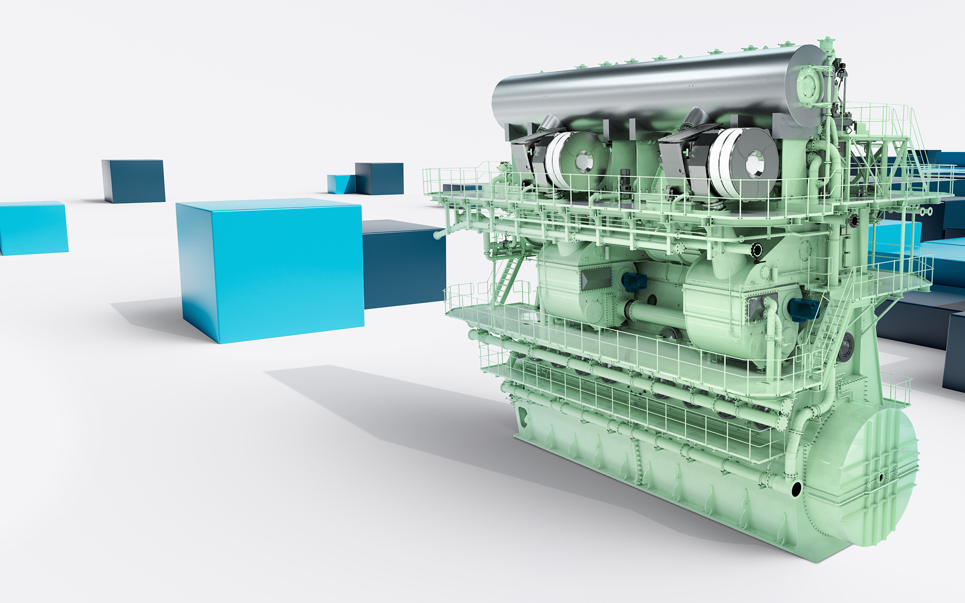
Marine diesel engines are the backbone of global shipping, propelling the majority of the world’s tonnage. The MAN B&W MC/ME engine is a prime example of modern marine diesel engine technology, known for its efficiency and reliability. This educational material provides an in-depth look at the construction and operational principles of the MAN B&W MC/ME engine, focusing on its key components and the thermodynamic processes involved.
Diesel engines are the primary propulsion systems for most ships due to their high efficiency and ability to convert thermal energy into mechanical energy with minimal fuel consumption.
Engineers monitor critical parameters such as exhaust gas and cooling water temperatures to ensure optimal engine performance.
Key Components of the MAN B&W MC/ME Engine
The engine consists of several movable and stationary parts that work together to convert fuel energy into mechanical work. Below are the primary components:
Movable Parts
- Piston: Converts the pressure from combustion into linear motion.
- Piston Rod: Transmits the force from the piston to the crosshead.
- Crosshead: Connects the piston rod to the connecting rod and transmits horizontal forces to the engine frame.
- Connecting Rod: Transfers the linear motion of the piston to the crankshaft.
- Crankshaft: Converts linear motion into rotational torque.
Stationary Parts
- Engine Frame: Supports the engine components and absorbs the horizontal forces from the crosshead.
- Guide Bars: Provide support and alignment for the crosshead shoes.
- Cylinder: Houses the piston and combustion process.
- Piston Rings: Seal the combustion chamber and prevent gas leakage.
Working Principle of a Two-Stroke Diesel Engine
The MAN B&W MC/ME engine operates on the two-stroke cycle, which consists of the following stages:
1 Scavenging
- Fresh air is supplied by a turbocharger and cooled before entering the scavenge air receiver.
- As the piston nears the bottom of its stroke, the exhaust valve opens, and scavenge ports are uncovered, allowing fresh air to flow into the cylinder and expel exhaust gases.
2 Compression
- The exhaust valve and scavenge ports close, and the piston moves upward, compressing the air in the cylinder.
- The compressed air heats up, preparing for fuel injection.
3 Combustion & Expansion
- Fuel is injected into the cylinder and ignites due to the high temperature of the compressed air.
- The combustion process increases the temperature and pressure, driving the piston downward.
- The high-pressure gases expand, transferring energy to the piston and crankshaft.
4 Exhaust
- The exhaust valve opens, and the remaining combustion products are expelled as fresh air enters the cylinder, restarting the cycle.
Thermodynamic Processes in the Cylinder
The engine’s performance is determined by the pressure and volume changes in the cylinder during the combustion cycle. These changes are represented by a PV Diagram (Indicator Diagram).
Indicator Diagram
- Compression Line: Represents the work done by the piston to compress the air.
- Expansion Line: Represents the work received by the piston during the power stroke.
- Net Work: The area between the compression and expansion lines indicates the net work output of the engine.
Temperature Changes
- During compression, the air temperature rises significantly, reaching up to 80°C.
- During combustion, the temperature peaks at approximately 1,900°C, exceeding the melting points of materials like aluminum and cast iron.
- Efficient cooling systems (oil and water) are essential to maintain safe operating temperatures and prevent damage to engine components.
Cooling Systems
The high temperatures generated during combustion necessitate effective cooling mechanisms:
Piston Cooling
- Oil is circulated through the piston rod and into the piston to absorb heat.
Cylinder Cooling
- Water circulates through the cooling jacket around the cylinder and cylinder head.
- Narrow drilled channels near heat-loaded surfaces enhance heat transfer.
Micro Boiling Phenomenon
- Local boiling of cooling water near the cylinder wall absorbs large amounts of heat, maintaining a stable wall temperature.
Performance Monitoring and Optimization
Modern engines are equipped with advanced monitoring systems to ensure optimal performance and reliability:
PMI System
- Replaces traditional indicator systems with high-quality data collection.
- Measures combustion chamber pressures and crankshaft position.
- Calculates mean indicated cylinder pressure and other performance metrics.
- Ensures load and cylinder balance remain within predefined limits.
Indicator Diagram Analysis
- Provides real-time data on pressure and volume changes in the cylinder.
- Helps engineers refine engine performance and diagnose issues.
Conclusion
The MAN B&W MC/ME engine exemplifies the efficiency and complexity of modern marine diesel engines. Understanding its construction, working principles, and thermodynamic processes is essential for ship engineers to ensure reliable and efficient operation. By leveraging advanced monitoring systems and maintaining effective cooling mechanisms, engineers can optimize engine performance and extend its service life.
Key Takeaways
- The MAN B&W MC/ME engine operates on a two-stroke cycle, consisting of scavenging, compression, combustion, expansion, and exhaust.
- Key components include the piston, piston rod, crosshead, connecting rod, and crankshaft.
- The PV diagram (indicator diagram) is a critical tool for analyzing engine performance.
- Efficient cooling systems are vital to managing the high temperatures generated during combustion.
- Advanced monitoring systems like the PMI system enhance engine reliability and performance.


