

Dynamic positioning ships explained: how DP systems hold station at sea, IMO guidance, DP classes, audits/trials, and operational best practices for safety.
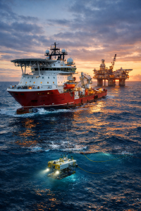
Imagine a vessel working offshore, in deep water, with no anchor on the seabed. Below the ship, a remotely operated vehicle (ROV) is inspecting a pipeline, or a subsea crane is lowering a heavy component, or divers are working in the water under strict time limits. The ship must remain steady—sometimes within a few metres—while wind, waves, and current keep pushing it away. In that moment, “good seamanship” is not only about steering well. It is about controlling a complex system that continuously balances forces and failures.
That is the world of dynamic positioning ships, often called DP vessels. A DP ship uses a dynamic positioning system—a combination of sensors, computers, power, and thrusters—to automatically maintain position and heading at sea.
DP is now foundational to offshore energy, subsea construction, cable laying, offshore wind, scientific research, and increasingly complex maritime projects. When DP works well, it enables precision work that would otherwise be impossible. When DP fails—or when operators misjudge the risks—the consequences can escalate quickly: drift-off from a safe zone, collision with an installation, damage to subsea infrastructure, injury during lifting operations, or pollution events. Because DP vessels often operate close to fixed structures and people, DP is not just “navigation technology.” It is a safety-critical operating mode that relies on redundancy, disciplined procedures, competent personnel, and continuous verification.
–
Key Developments, Technologies, and Principles Applications
What exactly is a dynamic positioning system?
A DP system is the complete installation necessary for dynamically positioning a vessel, typically comprising three major sub-systems: power system, thruster system, and DP control system.
This definition is important because it prevents a common misconception: DP is not “a joystick and a computer.” DP is a whole-ship capability. It includes the power plant, electrical distribution philosophy, thruster layout, control logic, sensors, reference systems, alarms, operator interfaces, and the human procedures that keep the vessel within safe limits.
A simple analogy helps non-specialists: if conventional shiphandling is like driving a car on a road, DP is like balancing a ball on a moving platform in strong wind—continuously, automatically, and with backup systems ready if one element fails.
DP vessels in the real world: where they are used
DP vessels exist because many offshore tasks cannot tolerate significant position error. The most common DP ship types include:
-
Offshore supply vessels (OSVs) supporting rigs and platforms
-
Construction vessels and heavy-lift ships performing precision lifts
-
Diving support vessels (DSVs) holding station for diver safety
-
Cable-laying and pipe-laying vessels needing exact track control
-
Shuttle tankers operating in DP modes during offshore loading (in some configurations)
-
Research vessels holding station for seabed sampling or acoustic surveys
Even within these categories, risk levels vary widely. “DP at sea” can mean a vessel maintaining station in open water, or a vessel working a few hundred metres from an installation. That difference changes everything about redundancy expectations, operational limits, and decision thresholds.
The three pillars: sensors, references, and control
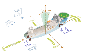
A DP control system needs to “understand” the vessel’s position, heading, and motion, and then calculate corrective thrust. It does this using multiple information streams:
Heading and motion sensors such as gyrocompasses and motion reference units provide heading and vessel movement characteristics.
Environmental sensors (especially wind sensors) help estimate external forces.
Position reference systems (PRS) provide absolute or relative position inputs—typically combinations of GNSS, acoustic systems, laser/optical references, taut wire, or microwave systems depending on the operational context and proximity to fixed objects.
The safety logic is straightforward: any single sensor can be wrong, and any reference can be degraded. A DP vessel therefore uses multiple sensors, redundancy, and monitoring so that erroneous data is detected before it drives unsafe thrust commands.
DP equipment classes: what “Class 1, 2, and 3” really mean
One of the most searched topics online is “DP Class 1 vs Class 2 vs Class 3.” DP equipment classes relate to fault tolerance—how the vessel should respond to failures.
In practical terms, the classes can be understood as:
DP equipment class 1: loss of position may occur in the event of a single fault. This may be acceptable for low-risk operations in open water where a drift-off does not create an immediate hazard.
DP equipment class 2: the system should be designed so that a single fault in an active component or system does not cause loss of position (fault-tolerant design with redundancy).
DP equipment class 3: higher fault tolerance, including protection against certain fire/flood scenarios through physical separation and redundancy, intended for the highest-risk operations near installations or where people are directly exposed.
The key point is not the label. The key point is that the DP class must match the operation’s consequence profile. If the consequence of losing position is severe, the class—and the operational discipline—must be stronger.
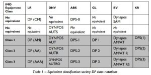
Redundancy design and class notations: how classification societies formalise DP capability
While IMO provides international guidance, classification societies translate DP expectations into class rules and notations. Additional class notations such as DPS and DYNPOS include design, documentation, certification, and testing requirements for DP systems.
This is where DP becomes concrete for ship design and verification. Redundancy is not a vague statement—it is implemented through electrical distribution philosophy (open vs closed bus), segregation, standby redundancy, thruster configuration, and failure consequence analysis.
Verification philosophy: FMEA, trials, and documented acceptance
DP is a system where “it worked yesterday” is not a sufficient argument. Because failures can be hidden until the system is stressed, DP guidance emphasises verification and testing.
In practice, verification typically includes:
-
Design review and documentation of redundancy and segregation
-
FMEA (Failure Modes and Effects Analysis) to understand what happens when components fail
-
Harbour acceptance tests and sea trials (often called DP trials)
-
Annual or periodic trials depending on flag/class/charter requirements
-
Operational checks before and during critical DP activities
The DP vessel is not merely “classed for DP.” It is continuously demonstrated to be capable of DP at the required risk level.
DP operations: maintaining safety through “watchkeeping logic”
DP operations are, in many respects, navigational watchkeeping plus engineering watchkeeping plus operations management—combined. The DP control system continuously commands thrusters, but humans remain responsible for:
-
selecting the correct DP mode and references for the activity;
-
maintaining sufficient power and thruster availability;
-
monitoring alarms and performance indicators;
-
applying operational limits (wind/current limits, thruster load limits, reference quality limits);
-
managing change, including degraded modes and planned maintenance.
This is why DP vessels typically use a dedicated operational framework: activity planning, checklists, DP logs, defined roles (including DP operator), and clear escalation pathways.
–
Challenges and Practical Solutions (narrative, operationally focused)
Challenge 1: Hidden common-mode failures
DP failures are rarely dramatic component explosions. More often, they are common-mode failures—events that defeat multiple redundant elements at once. Examples include shared cooling systems, shared switchboard vulnerabilities, incorrect configuration, software issues, or a power management system that behaves unexpectedly under load.
Practical solution: treat redundancy as a real engineering architecture, not a marketing term. Verification should include realistic failure testing (within safety boundaries) and clear documentation of what a single fault means for the vessel in different operational modes.
Challenge 2: Position reference degradation and GNSS vulnerability
GNSS is powerful, but it can be degraded by interference, multipath, antenna issues, or deliberate spoofing in some regions. DP systems typically combine multiple references, but the risk remains: if bad reference data is not detected, the system may “hold” a false position.
Practical solution: use multiple independent position references and maintain a disciplined approach to reference selection, monitoring, and alarms. Train crews to recognise early signs of reference divergence and to execute controlled responses (including fallback references or safe disconnection when required).
Challenge 3: Human factors—automation can reduce alertness
DP can create a psychological trap: when the system is stable for hours, attention can drift. Yet DP risks often emerge suddenly—when weather shifts, when thruster availability changes, or when a reference fails.
Practical solution: structure the DP watch so it stays active. A good DP watch is not passive screen-watching. It includes continuous trend monitoring, periodic redundancy checks aligned with the activity, active communication with the bridge team and engine control room, and a culture where raising concerns is rewarded rather than criticised.
Challenge 4: Degraded modes and decision timing
A DP vessel rarely fails instantly. More commonly, it enters a degraded state: one thruster trips, a generator alarms, a reference becomes unstable, or a critical sensor drops out. The dangerous moment is not the alarm itself—it is the delay in decision-making, especially when the vessel remains “apparently stable” for a short time.
Practical solution: define clear operational limits and triggers in activity planning. Many organisations use structured operational guidance (often built around consequence analysis and worst-case failure assumptions) so that when capability reduces, the crew is not improvising.
Challenge 5: Power plant stress and energy cost
DP is energy-intensive. Thrusters consume fuel continuously to counter environmental forces, and power redundancy requirements can keep additional generators online. As shipping decarbonises, DP operations will face increasing pressure to be efficient without compromising safety.
Practical solution: treat efficiency as a controlled optimisation problem rather than a cost-cutting exercise. Improve hull/propulsor condition, optimise thruster use (where safe), tune power management systems, and apply operational planning that minimises time on DP when not required. The safety case must always dominate, but disciplined operations can reduce unnecessary consumption.
Challenge 6: Assurance complexity—multiple stakeholders, multiple standards
DP assurance often involves flag requirements, class rules, charterer expectations, and industry guidance. This can lead to confusion: crews may be uncertain whether a trial requirement comes from class notation, charter contract, or internal SMS procedures.
Practical solution: integrate DP assurance into the ship’s Safety Management System with clarity: what is mandatory, what is contractual, and what is best practice. Centralise DP documentation, align terminology, and ensure DP verification evidence is easy to retrieve and understand during inspections and audits.
–
Case Studies and Real-World Applications (descriptive narrative)
Case Study 1: Offshore construction near a platform—when “small drift” is not small
Consider a construction vessel working near a fixed offshore installation. The DP system is holding position well, but wind increases and one thruster begins to overheat. The vessel remains stable, but power margin narrows. The DP operator now faces a subtle risk: if another thruster trips, the vessel might not hold station, and the drift could become rapid due to proximity constraints.
What makes this scenario realistic is that nothing looks catastrophic at first. The ship still “appears” in control. This is exactly why DP guidance emphasises design redundancy, operating requirements, and structured verification. The goal is not only to prevent failure, but to manage degraded capability safely, with decisions made early rather than late.
Case Study 2: Cable laying—DP as precision navigation
Cable laying operations require the vessel to follow a planned route at low speed while maintaining tension and avoiding seabed hazards. Here DP becomes a form of precision navigation, integrating reference systems, track control, and careful power management.
Case Study 3: Audit and acceptance—why documentation matters when something goes wrong
When a DP incident occurs, investigators and stakeholders typically ask two questions immediately: (1) what failed, and (2) what evidence existed that the system was suitable for the operation. That evidence is found in design verification, FMEA, trials, periodic tests, maintenance records, DP logs, and operational planning documentation.
–
Future Outlook and Maritime Trends
Digitalisation and condition-based assurance
DP systems already generate large volumes of data—thruster loads, power margins, reference quality, alarm history, and control modes. The future trend is to turn this data into condition-based assurance: predictive maintenance, early warning of reference instability, and better understanding of how close the vessel operated to its limits during critical tasks.
This does not remove the need for competent crews. If anything, it increases the need for operators who understand what the system is doing and can interpret trends rather than reacting only to alarms.
DP in offshore wind and new marine industries
Offshore wind construction and maintenance continues to expand globally, driving demand for DP-capable vessels such as service operation vessels (SOVs), construction vessels, and cable layers. DP is becoming a mainstream competence, not a niche offshore skill.
As the sector grows, standardisation pressures increase: more consistent training, clearer verification expectations, and closer alignment between IMO guidance, class rules, and charterer requirements.
Cyber and resilience expectations
DP systems are integrated with bridge networks and vessel control architectures, making resilience and cyber-aware operations increasingly important. The practical future is likely to include stronger segregation, improved monitoring, and operational drills that include “data integrity” failures—not only mechanical failures.
Energy transition and hybrid power
Hybrid power systems, energy storage, and advanced power management may help optimise DP energy use while maintaining redundancy. The challenge will be to prove reliability under DP failure cases and to integrate new technology into verification frameworks. Class rules and DP guidance will continue to evolve as these architectures become more common.
–
FAQ Section
1) What is a dynamic positioning (DP) ship?
A DP ship is a vessel that uses a DP system—power, thrusters, and control system with sensors/reference inputs—to automatically maintain position and heading at sea.
2) Is “DP Class 2” the same everywhere?
The concept is broadly consistent (fault tolerance), but detailed expectations can vary by IMO guidance interpretation, class rules, and charterer requirements.
3) Why do DP vessels need redundancy?
Because a single failure can otherwise lead to loss of position, which may be unacceptable near installations or during high-risk tasks. Redundancy and fault tolerance are central design and operational principles.
4) What is the difference between DP equipment classes 1, 2, and 3?
They relate to how the vessel should respond to failures and the level of redundancy and segregation expected. Higher classes are intended for higher-consequence operations.
5) What is an FMEA in DP context?
A Failure Modes and Effects Analysis identifies how component failures affect DP capability and supports verification and safe operational planning (especially for worst-case failure conditions).
6) Can GNSS problems affect DP safety?
Yes. If GNSS signals degrade or are manipulated, position references can become unreliable. DP operations should use multiple independent references and strong monitoring to detect divergence.
7) Who sets DP standards—IMO or classification societies?
Both contribute. IMO provides international guidelines, while classification societies implement technical requirements through class rules and DP notations such as DPS/DYNPOS frameworks.
–
Conclusion
Dynamic positioning ships are among the most capable—and most demanding—vessels at sea. They make modern offshore work possible by holding station with high precision, but they do so by balancing complex interactions between power, thrusters, sensors, reference systems, and human decision-making.
The practical lesson from decades of offshore operations is consistent: DP safety is not achieved by buying a DP system. It is achieved by designing for fault tolerance, verifying performance through structured trials and documentation, and operating with disciplined watchkeeping and clear decision thresholds.
If your platform trains mariners, supports offshore projects, or manages DP-capable fleets, the best investment is competence plus verification: train crews to think in failure cases, keep documentation honest and usable, and treat DP as a safety-critical operating mode—every time.
–
References
International Maritime Organization. (1994). MSC/Circ.645: Guidelines for vessels with dynamic positioning systems.
International Maritime Organization. (2017). MSC.1/Circ.1580: Guidelines for vessels and units with dynamic positioning (DP) systems.
International Marine Contractors Association (IMCA). (n.d.). Guidelines for the design and operation of dynamically positioned (DP) vessels (IMCA guidance resource page).
DNV. (2019). DNVGL-RU-SHIP Pt.6 Ch.3: Navigation, manoeuvring and position keeping (additional class notations DPS and DYNPOS).